Dismantling Document
Rev 1.1
7
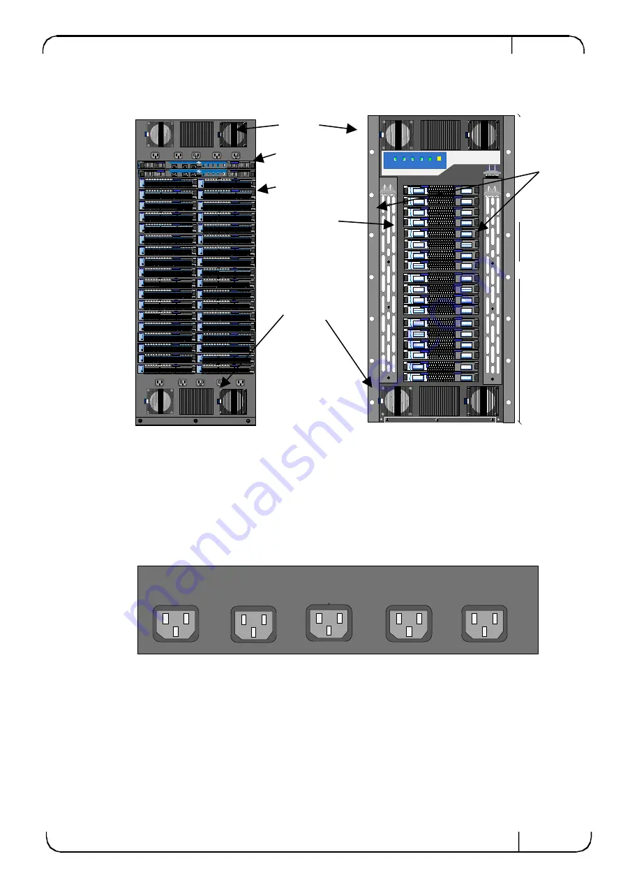
Figure 1: Front and Rear View of the MIS5600
2
Extraction of the Modules
2.1 Extracting the Power Supply Units (PSU)
To extract a PSU:
1.
Remove all of the power cords from the chassis. These are on the connector side.
Figure 2: Power Cord Top Bar
2.
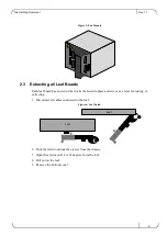
Move around to the spine side and remove the power supply covers. Odd numbered PSUs
are on the left side and even numbered PSUs are on the right side facing the spines. There
are four Phillips head screws for the cover plates. See Figure 3: Power Supply Covers for
the location of the PSU covers.
MGT
CONSOLE
RST
I2C
Master
L.Fans
S.Fans
PSU
MGT
CONSOLE
RST
I2C
PSU
Master
L.Fans
S.Fans
AC6
AC7
AC8
AC9
AC10
AC1
AC2
AC3
AC4
AC5
1285mm
S1
S2
S3
S4
S5
S6
S7
S8
S9
S10
S11
S12
S13
S14
S15
S16
S17
S18
Mellanox
IS5600
IS5600
Mellanox
IS5600
IS5600
Mellanox
AC1
AC2
AC3
AC4
AC5
Power modules
are behind the
covers.
Fans
Management
Modules
Leafs
Spines
Cover to
PSUs
Fans

