background image

Rev 1.2

Mellanox Technologies

7

List of Tables

Table 1:

Revision History Table . . . . . . . . . . . . . . . . . . . . . . . . . . . . . . . . . . . . . . . . . . . . . . . . . . . . 8

Table 2:

References   . . . . . . . . . . . . . . . . . . . . . . . . . . . . . . . . . . . . . . . . . . . . . . . . . . . . . . . . . . . . . 9

Table 3:

Speed and Switching Capabilities   . . . . . . . . . . . . . . . . . . . . . . . . . . . . . . . . . . . . . . . . . . 12

Table 4:

Management Interfaces and FRUs  . . . . . . . . . . . . . . . . . . . . . . . . . . . . . . . . . . . . . . . . . . 12

Table 5:

Ordering Part Numbers (OPNs)  . . . . . . . . . . . . . . . . . . . . . . . . . . . . . . . . . . . . . . . . . . . . 13

Table 6:

Air Flow Color Legend . . . . . . . . . . . . . . . . . . . . . . . . . . . . . . . . . . . . . . . . . . . . . . . . . . . 16

Table 7:

Installation Kit   . . . . . . . . . . . . . . . . . . . . . . . . . . . . . . . . . . . . . . . . . . . . . . . . . . . . . . . . . 18

Table 8:

Installation Kit   . . . . . . . . . . . . . . . . . . . . . . . . . . . . . . . . . . . . . . . . . . . . . . . . . . . . . . . . . 23

Table 9:

Installation Kit   . . . . . . . . . . . . . . . . . . . . . . . . . . . . . . . . . . . . . . . . . . . . . . . . . . . . . . . . . 28

Table 10: Serial Terminal Program Configuration  . . . . . . . . . . . . . . . . . . . . . . . . . . . . . . . . . . . . . . 36
Table 11: Configuration Wizard Session  . . . . . . . . . . . . . . . . . . . . . . . . . . . . . . . . . . . . . . . . . . . . . 37
Table 12: Configuration Wizard Session - Static IP Configuration  . . . . . . . . . . . . . . . . . . . . . . . . . 38
Table 13: LEDs Symbols  . . . . . . . . . . . . . . . . . . . . . . . . . . . . . . . . . . . . . . . . . . . . . . . . . . . . . . . . . 46
Table 14: System Status LED Assignments  . . . . . . . . . . . . . . . . . . . . . . . . . . . . . . . . . . . . . . . . . . . 47
Table 15: Fan Status Front LED Assignments  . . . . . . . . . . . . . . . . . . . . . . . . . . . . . . . . . . . . . . . . . 48
Table 16: Fan Status Rear LED Assignments (One LED per Fan)   . . . . . . . . . . . . . . . . . . . . . . . . . 48
Table 17: Power Supply Unit Status Front LED Assignments . . . . . . . . . . . . . . . . . . . . . . . . . . . . . 49
Table 18: Power Supply Unit Status Rear LED Assignments  . . . . . . . . . . . . . . . . . . . . . . . . . . . . . 49
Table 19: Bad Port LED Assignments  . . . . . . . . . . . . . . . . . . . . . . . . . . . . . . . . . . . . . . . . . . . . . . . 50
Table 20: Port LEDs in Ethernet System Mode  . . . . . . . . . . . . . . . . . . . . . . . . . . . . . . . . . . . . . . . . 51
Table 21: Troubleshooting  . . . . . . . . . . . . . . . . . . . . . . . . . . . . . . . . . . . . . . . . . . . . . . . . . . . . . . . . 54
Table 22: SN2700 Specifications  . . . . . . . . . . . . . . . . . . . . . . . . . . . . . . . . . . . . . . . . . . . . . . . . . . . 56
Table 23: SN2410 Specifications  . . . . . . . . . . . . . . . . . . . . . . . . . . . . . . . . . . . . . . . . . . . . . . . . . . . 58
Table 24: OPNs for Replacement Parts   . . . . . . . . . . . . . . . . . . . . . . . . . . . . . . . . . . . . . . . . . . . . . . 59

Summary of Contents for Spectrum SN2410

Page 1: ...www mellanox com Mellanox 1U Switch Systems Hardware User Manual Models SN2700 and SN2410 Rev 1 2...

Page 2: ...T PRODUCT S AND ITS RELATED DOCUMENTATION ARE PROVIDED BY MELLANOX TECHNOLOGIES AS IS WITH ALL FAULTS OF ANY KIND AND SOLELY FOR THE PURPOSE OF AIDING THE CUSTOMER IN TESTING APPLICATIONS THAT USE THE...

Page 3: ...Mounting Telescopic Rail Kit for SN2700 23 2 4 3 19 Systems Mounting Static Rail Kit for SN2410 28 2 5 Cable Installation 32 2 5 1 Breakout Cables and Adapters 32 2 6 Initial Power On 34 2 7 System B...

Page 4: ...y and Disposal 66 D 1 Disassembly Procedure 66 D 2 Disposal 66 Appendix E Safety Warnings Multiple Languages 67 E 1 Nordic Countries Notices 67 E 2 Installation Safety Warnings English 67 E 3 Hebrew 7...

Page 5: ...igure 15 Installing the Cage Nuts 25 Figure 16 Mounting the Outer Rails into the Rack 25 Figure 17 Attaching the Inner Rails to the Chassis 26 Figure 18 Securing the Chassis in the Inner Rails 26 Figu...

Page 6: ...ure 39 Rear Side Panel 49 Figure 40 SN2700 Port LEDs 51 Figure 41 SN2410 SFP28 Port LEDs 51 Figure 42 SN2410 QSFP28 Port LEDs 51 Figure 43 SN2700 Pull out Tab 52 Figure 44 SN2410 Inventory Information...

Page 7: ...onfiguration Wizard Session 37 Table 12 Configuration Wizard Session Static IP Configuration 38 Table 13 LEDs Symbols 46 Table 14 System Status LED Assignments 47 Table 15 Fan Status Front LED Assignm...

Page 8: ...16 1 2 Updated Introduction to Mellanox SN2XXX Spectrum Ethernet Switch Systems Software Management Troubleshooting Instructions Specifications Accessory and Replacement Parts Added Taiwan BSMI Class...

Page 9: ...cription MLNX OS User Manual This document contains information regarding the configuration and man agement of the MLNX OS software See http www mellanox com page mlnx_os Cumulus Linux User Guide This...

Page 10: ...Rev 1 2 Mellanox Technologies 10 This icon indicates a situation that can potentially cause damage to hardware or software This icon indicates a situation that can potentially cause personal injury...

Page 11: ...lieves some of the major obstacles standing in the way when deploying a network NEO enables a fully certified and interoperable design speeds up time to service and RoI The systems introduce hardware...

Page 12: ...nformation see Breakout Cables and Adapters 1 3 Management Interfaces and FRUs Table 4 lists the various management interfaces and available replacement parts per system model Table 3 Speed and Switch...

Page 13: ...Kit RoHS6 MSN2700 CS2R Spectrum based 100GbE 1U Open Ethernet Switch with MLNX OS 32 QSFP28 ports 2 Power Supplies AC Standard depth x86 CPU C2P airflow Rail Kit RoHS6 MSN2700 CS2FO Spectrum based 100...

Page 14: ...lus Linux 48 SFP28 ports 8 QSFP28 ports 2 power supplies AC x86 dual core Short depth P2C airflow Rail Kit RoHS6 MSN2410 BB2RC Spectrum based 10GbE 40GbE 1U Open Ethernet switch with Cumulus Linux 48...

Page 15: ...rdic Countries Notices see Section E 1 Nordic Countries Notices on page 67 For Safety Warnings in English see Section E 2 Installation Safety Warnings English on page 67 For Safety Warnings in Hebrew...

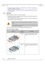
Page 16: ...nlet to power side outlet marked with red power supplies fans FRUs handles as shown in figure Figure 5 Table 6 provides an air flow color legend and respective OPN designations All servers and systems...

Page 17: ...Package Contents Before installing your new system unpack it and check against the parts list below that all the parts have been sent Check the parts for visible damage that may have occurred during...

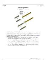
Page 18: ...the Static Rail kit see Figure 6 2x Rack mount rails A 2x Rack mount brackets B 2x Rack mount blades C 8x M6 Standard cage nuts and 8x M6 Standard pan head Phillips screws D 4x Phillips100 DEG F H TY...

Page 19: ...points Make sure the system air flow is compatible with your installation selection It is important to keep the airflow within the rack in the same direction Note that the part of the system to which...

Page 20: ...s by screwing 2 flat head Phillips screws E in the designated points with a torque of 1 5 0 2 Nm See Figure 8 Figure 8 Attaching the Rails to the Chassis Step 3 Attach the left and right rack mount br...

Page 21: ...ile your installation partner is supporting the system s weight perform the following steps Step 5 Mount the system into the rack enclosure and attach the brackets installed on the system to the rack...

Page 22: ...of 4 5 0 5 Nm 2 4 1 1 Removing the System from the Rack To remove a unit from the rack Step 1 Turn off the system and disconnect it from peripherals and from the electrical outlet While your installa...

Page 23: ...rails C 2x Outer rails D 10x M6 Standard cage nuts and 10x M6 Standard pan head Phillips screws E 2x Phillips100 DEG F H TYPE I ST ST 6 32 X 1 4 screw with around patch F Other threads are available...

Page 24: ...gure 14 Rails Separation To separate the rails 1 Extend the rail assembly by pulling the extension outwards D 2 Extract rail A from rail C by pushing it outside from the rear part of the assembly To a...

Page 25: ...lacement of the system s rails The FRU side is extractable Mounting the sliding rail inverted to the system will allow you to slide the FRU side of the system in and out Step 1 Install 10 cage nuts in...

Page 26: ...ecure the chassis in the inner rails by screwing the 2 flat head Phillips screws F in the desig nated points with a torque of 1 5 0 2 Nm Figure 18 Securing the Chassis in the Inner Rails Step 6 Slide...

Page 27: ...2 1 Removing the System from the Rack To remove a unit from the rack Step 1 Turn off the system and disconnect it from peripherals and from the electrical outlet Step 2 Unscrew the two M6 screws secu...

Page 28: ...are included in the Static Rail kit see Figure 6 2x Rack mount rails A 2x Rack mount blades B 8x M6 Standard cage nuts and 8x M6 Standard pan head Phillips screws C At least two people are required t...

Page 29: ...ompatible with your installation selection It is important to keep the airflow within the rack in the same direction Note that the part of the system to which you choose to attach the rails the front...

Page 30: ...ach side a total of 4 screws See Figure 24 To tighten the screws use a torque of 1 5 0 2 Nm Figure 24 Attaching the Rails to the Chassis Step 2 Install 8 cage nuts C in the desired 1U slots of the rac...

Page 31: ...g four M6 screws C Do not tighten the screws yet See Figure 26 Figure 26 Attaching the Rails to the Rack Step 4 Slide the two blades into the left and right rails and adjust them to fit your rack s de...

Page 32: ...f Mellanox Cable Man agement Guidelines and FAQ For more information about port LEDs refer to Port LEDs Figure 28 Cable Orientation 2 5 1 Breakout Cables and Adapters A 100GbE port can be split to two...

Page 33: ...chd service using the sudo systemctl restart switchd command For more details see Layer 1 and Switch Port Attributes in the Cumulus Linux User Guide Figure 29 Breakout or Fanout Cables 2 5 1 3 SN2700...

Page 34: ...h normal operation initially flashing and then moving to a steady color as shown in Figure 32 below For more information refer to LEDs The system platform will automatically power on when AC power is...

Page 35: ...the green System Status LED light is on make sure that the Fan Status LED shows green If the Fan Status LED is not green unplug the power connection and check that the fan module is inserted properly...

Page 36: ...Step 3 Login as admin and use admin as password On the first login the MLNX OS configuration wizard will start Step 4 To configure network attributes and other initial parameters to the system follow...

Page 37: ...to use IPv6 addresses If you enter no no IPv6 you will automatically be referred to Step 6 Step 4 Enable IPv6 auto config SLAAC on mgmt0 interface no This turns on auto configuration of the IPv6 addre...

Page 38: ...imary IP address for example 192 168 10 4 10 10 10 10 Mask length may not be zero if address is not zero interface eth0 Step 5 Netmask 0 0 0 0 255 255 255 0 Step 6 Default gateway for example 192 168...

Page 39: ...eps Step 1 Set up an Ethernet connection between the system and a local network machine using a stan dard RJ45 connector Step 2 Start a remote secured shell SSH using the command ssh l username IP_add...

Page 40: ...placeable power supply units work in a redun dant configuration Either unit may be extracted without bringing down the system To extract a power supply unit Step 1 Remove the power cord from the power...

Page 41: ...p 5 Insert the other end of the power cord into an outlet of the correct voltage 2 8 2 Fans The system can fully operate if one fan FRU is dysfunctional or missing Failure of more than one fan is not...

Page 42: ...insert a fan unit Step 1 Make sure the mating connector of the new unit is free of any dirt and or obstacles Step 2 Insert the fan unit by sliding it into the opening until slight resistance is felt C...

Page 43: ...he CLI or the GUI in order to perform software upgrades For further information please refer to the MLNX OS Software User Manual section Upgrading MLNX OS Software Be sure to read and follow all of th...

Page 44: ...rts 4 1 2 Speed Ethernet speed must be set manually The system s ports can be manually configured to run at speeds ranging from 1GbE to 100GbE for more details see Specifications To change the port sp...

Page 45: ...em next to the fan status LEDs This reset button requires a tool to be pressed To reset the system and the CPU of its management board push the reset button and keep it pressed for up to 15 seconds To...

Page 46: ...13 LEDs Symbols Symbol Name Description Normal Conditions System Status LED Shows the health of the system Green Flashing green when booting Fan Status LED Shows the health of the fans Green Power su...

Page 47: ...your Mellanox representative for assistance Table 14 System Status LED Assignments LED Behavior Description Action Required Solid Green The system is up and running nor mally N A Flashing Green The sy...

Page 48: ...unit that indicates the status of the unit Table 15 Fan Status Front LED Assignments LED Behavior Description Action Required Solid Green All fans are up and running N A Solid Red Error one or more f...

Page 49: ...the FRUs might be faulty and should then be replaced Off N A N A Table 18 Power Supply Unit Status Rear LED Assignments LED Behavior Description Action Required Solid Green The PSU is running normally...

Page 50: ...l errors in one or more system ports Table 19 shows the bad port status LED assignment Table 19 Bad Port LED Assignments LED Configuration Description Action Required Off No symbol errors have been re...

Page 51: ...een If the ports run at a 50GbE speed each the left LEDs 1 and 2 will light green for the upper port and the right LEDs 3 and 4 will light green for the lower port If the ports run at a 25GbE speed ea...

Page 52: ...parameters such as serial number part number GUID and MAC address can be extracted from the inventory pull out tab on the lower right side of the front panel In some systems there is no pull out tab a...

Page 53: ...Interfaces Rev 1 2 Mellanox Technologies 53 Figure 45 SN2410 Inventory Information Illustration...

Page 54: ...the software status You might need to contact an FAE if the MLNX OS software did not load properly System Status LED is red This state can indicate a number of problems Critical system fault CPU error...

Page 55: ...or boot menu Booting default image in 3 seconds Boot Menu 0 SX_X86_64 SX_3 4 0008 2014 11 10 20 07 51 x86_64 1 SX_X86_64 SX_3 4 0007 2014 10 23 17 27 34 x86_64 Use the ArrowUp and Arrowdown keys to se...

Page 56: ...ure Operational 0 to 45 C Non Operational 40 to 70 C Humidity Operational 10 85 non condensing Non Operational 10 90 non condensing Altitude 3050m Regulatory Safety CS cTUVus CE CU EMC CE FCC VCCI ICE...

Page 57: ...Specifications Rev 1 2 Mellanox Technologies 57 Switching Capacity 6 4Tb s Table 22 SN2700 Specifications Feature Value...

Page 58: ...erational 10 85 non condensing Non Operational 10 90 non condensing Altitude 3050m Regulatory Safety CS cTUVus CE CU EMC CE FCC VCCI ICES RCM RoHS6 Power Input Voltage 100 127Vac 50 60Hz 4 5A 200 240...

Page 59: ...U wide systems to be mounted into short depth racks MTEF KIT SP Rack installation kit for 1U wide systems to be mounted into standard depth racks MTEF PSF AC A 460W AC Power Supply w rear to front air...

Page 60: ...the switch has crossed the Warning threshold Note that this temperature threshold does not require nor lead to any action by hardware such as switch shutdown Critical 120 C When the device crosses th...

Page 61: ...9 ResetL Module Reset 10 Vcc Rx 3 3 V Power supply receiver 11 SCL 2 wire serial interface clock 12 SDA 2 wire serial interface data 13 GND Ground 14 Rx3p Receiver Non Inverted Data Output 15 Rx3n Rec...

Page 62: ...8 3 3 3 3 3 3 3 3 RX4p GND GND GND RX4n RX2p RX2n TX1n GND TX1p GND TX3n TX3p GND IntL ModPrsL VccTx Vcc1 LPMode 18 35 8 50 Top ResetL SDA SCL ModSelL RX3p TX2n GND VccRx 1 2 3 4 5 6 7 8 9 10 1 2 3 4...

Page 63: ...ment Mellanox Technologies MTSFPP SR Module 14 80 13 60 56 50 13 70 1 80 1 55 44 95 8 50 2 55 0 50 0 60 13 90 11 85 13 70 8 50 Top VeeT VeeT VeeT TX_Fault TX_Disable SDA SCL MOD_ABS RS0 RX_LOS RS1 Vee...

Page 64: ...st board to a voltage between 2 0V and 3 6V MOD_ABS pulls line low to indicate module is plugged in 5 SCL 2 wire Serial Interface Clock Line d 6 MOD_ABS Module Absent Grounded within the module d 7 RS...

Page 65: ...Mellanox Technologies 65 C 3 RJ45 to DB9 Harness Pinout In order to connect a host PC to the Console RJ45 port of the system a RS232 harness cable DB9 to RJ45 is supplied Figure 48 RJ45 to DB9 Harness...

Page 66: ...7 Remove the caged nuts D 2 Disposal Follow the instructions found at http www mellanox com page dismantling_procedures for proper disassembly and disposal of the switch according to the WEEE directi...

Page 67: ...llation instructions before connecting the equipment to the power source Use enough people to safely lift this product This equipment is heavy and should be moved using a mechanical lift to avoid inju...

Page 68: ...s double pole neutral fusing Remove all power cords before opening the cover of this product or touching any internal parts Risk of electric shock and energy hazard The PSUs are all independent Discon...

Page 69: ...g Replace only with UL Recognized battery certified for maximum abnormal charging current not less than 4mA There is a risk of explosion should the battery be replaced with a battery of an incorrect t...

Page 70: ...rated in the building wiring Caution Slide rail mounted equipment is not to be used as a shelf or a work space The rails are not intended for sliding the unit away from the rack It is for permanent in...

Page 71: ...Rev 1 2 Mellanox Technologies 71 2 3 4 5 6 7 40 lbs 18 kgs 40 70 lbs 18 32 kgs 70 121 lbs 32 55 kgs 121 lbs 55 kgs...

Page 72: ...Mellanox Technologies 72 8 9 10 11 12 13...

Page 73: ...Rev 1 2 Mellanox Technologies 73 14 15 16 17 18 19...

Page 74: ...Mellanox Technologies 74 20 21 WEEE 22 E 4 Chinese 1 2 40 lbs 18 kgs 40 70 lbs 18 32 kgs 70 121 lbs 32 55 kgs 121 lbs 55 kgs...

Page 75: ...Rev 1 2 Mellanox Technologies 75 3 4 5 6 7 8 9 45 C 113 F 8 3 PSU...

Page 76: ...Mellanox Technologies 76 10 11 12 13 14 15 16 UL 4mA...

Page 77: ...Rev 1 2 Mellanox Technologies 77 17 UL CSA 18 19 20 21 22 WEEE UL CSA 16 AWG 125 V 13 A 1 5 4 5 HAR 1 0 300 V PVC 250 V 10 A RS232 UL DP 1 DP 2 LPS 20 A WEEE 2002 96 EC EEE...

Page 78: ...Mellanox Technologies 78 23 24 China CCC Warning Statement TN IT...

Page 79: ...Cet quipement est lourd et doit tre d plac avec un syst me de levage m canique pour viter les blessures Danger d lectrocution Lorsque le module de ventilation est retir les broches d alimentation son...

Page 80: ...bles phase neutre D branchez tous les cordons d alimenta tion avant d ouvrir le capot ou de toucher tout l ment l int rieur Risque et danger d lectrocution Les alimentations sont toutes ind pendantes...

Page 81: ...nal Electrical Code et du Code canadien de l lectricit Avertissement ne remplacer qu avec une batterie UL certifi e pour accepter un cou rant de charge anormal maximal sup rieur ou gal 4 mA Si la batt...

Page 82: ...ensit s le c blage de l immeuble doit int grer un dispositif certifi de protection contre les surintensit s calibr 20 A et ais ment accessible Attention un quipement coulissant ou mont sur rail ne doi...

Page 83: ...m Bereich mit einer Umgebungstemperatur ber der maximal empfohlenen Temperatur von 45 C 113 F betrieben werden Es ist ein Luft strom von 200 LFM bei maximaler Umgebungstemperatur erforderlich Au erdem...

Page 84: ...rkabel sind schwer und nicht flexible Deshalb m ssen sie vorsichtig an die Anschl sse angebracht bzw davon getrennt werden Lesen Sie die speziellen Warnun gen und Anleitungen des Kabelherstellers Wenn...

Page 85: ...er bewertet bei 125 V 15 mit einer Mindestl nge von 1 5 m Six Feet aber nicht mehr als 4 5 m F r die europ ischen Zusammenhang w hlen Sie ein Netzkabel das international harmonisiert und der Aufschrif...

Page 86: ...ltigen Stan dort gedacht nicht f r Instandhaltung und Wartung Gem WEEE Directive 2002 96 EC m ssen alle elektrischen und elektronischen Abfallger te EEE separat gesammelt und nichit mit normalem Haush...

Page 87: ...r como m nimo un espacio de 8 cm 3 pulgadas alrededor de las aberturas de ventilaci n Los chasis no se deben apilar sobre otros equipos La ca da del chasis podr a causar lesiones corporales as como da...

Page 88: ...zando desde abajo hacia arriba La instalaci n el reemplazo y el mantenimiento de este equipo estar n a cargo nica mente de personal capacitado y competente La eliminaci n definitiva de este equipo se...

Page 89: ...ciente de los c digos el ctricos nacionales del pa s en cuesti n En Am rica del Norte el equipo se debe instalar de acuerdo con las disposiciones vigentes del C digo El ctrico Nacional de los EE UU y...

Page 90: ...Mellanox Technologies 90 E 8 Rus sian 1 2 3 4 5 6 45 C 113 F 8 3 40 lbs 18 kgs 40 70 lbs 18 32 kgs 70 121 lbs 32 55 kgs 121 lbs 55 kgs...

Page 91: ...Rev 1 2 Mellanox Technologies 91 7 8 9 10 11 12 13...

Page 92: ...Mellanox Technologies 92 14 15 16 17 18 UL CSA 19 UL 4 UL CSA 3 16 AWG 1 5 6 4 5 125 13 HAR 3 1 0 300 250 10...

Page 93: ...nologies 93 20 21 22 23 WEEE E 9 Avertismente privind siguran a la instalare Romanian 1 Instruc iuni de instalare RS232 Ethernet DP 1 DP 2 UL 20 2002 96 EC WEEE Citi i toate instruc iunile de instalar...

Page 94: ...trumente sau p r i din corp n cavitatea modulului ventilator Acest echipament nu trebuie s fie ac ionat ntr o zon unde temperatura ambiant dep e te valoarea maxim recomandat 45 C 113 F n plus pentru a...

Page 95: ...energie pentru a asigura decuplarea n inter iorul platformei de comutare n timpul perioadelor cu desc rc ri electrice luminoase nu lucra i cu echipamentul sau nu conecta i sau deconecta i cablurile Ca...

Page 96: ...mitate cu instruc iunile Pentru conectarea la o surs de alimentare pentru America de Nord selecta i un cordon de alimentare care este nregistrat UL i certificat CSA cu 3 conductoare 16 AWG terminat cu...

Page 97: ...trebuie s fie integrat n cablajul cl dirii Aten ie Echipamentul montat pe o linie de alunecare in nu va fi utilizat ca raft sau spa iu de lucru Scopul inelor nu este de a glisa unitatea de pe rack Ac...

Page 98: ...t ili dijelove tijela u otvor modula ventilatora Ovom se opremom ne bi trebalo rukovati u podru jima s temperaturom okoline koja prema uje najvi e preporu ene vrijednosti 45 C 113 F Osim toga kako bi...

Page 99: ...a kako biste osigurali stanje bez napajanja unutar platforme preklopnika Tijekom djelovanja munja nemojte raditi na opremi ili spajati ili odspajati kabele Bakreni kabeli su te ki i nesavitljivi i kao...

Page 100: ...baterija zamijeni neodgovaraju om vrstom Odlo ite prazne baterije sukladno uputama Za sjevernoameri ku mre u odaberite kabel napajanja koji je na UL listi i sa CSA certifikatom 3 ilni 16 AWG 16 AWG ko...

Page 101: ...ugraditi u o i enje zgrade Pozor Oprema montirana na kliza e vodilice ne bi se trebala koristiti kao polica ili radna povr ina Vodilice nisu namijenjene za povla enje ure aja iz ormari a Slu e samo za...

Page 102: ...erire strumenti o parti del corpo nella cavit del modulo della ventola Questa apparecchiatura non va utilizzata in un area con una temperatura ambiente superiore a quella massima consigliata 45 C 113...

Page 103: ...mmutatore non sia sotto tensione Durante i temporali non effettuare interventi sull apparecchiatura e non collegare o scollegare i cavi I cavi di rame sono pesanti e non flessibili Di conseguenza vann...

Page 104: ...chio di esplosione Smaltire le batterie usate in conformit con le istruzioni Per una connessione di alimentazione nordamericana selezionare un cavo di alimentazione di tipo UL e munito di certificazio...

Page 105: ...za nominale pari a 20 Attenzione un apparecchiatura scorrevole o montata su binari non va utilizzata come scaffale o piano di lavoro I binari non sono progettati per far scorrere e allontanare l unit...

Page 106: ...va ak sa lamak i in havaland rma deliklerinin etraf nda en az 8 cm 3 in a kl k b rak lmal d r Bu ekipman nerilen maksimum ortam s cakl n a an alanlarda al t r lmamal d r 45 C 113 F Ayr ca d zg n hava...

Page 107: ...Anahtar platformundaki g c kapatmak i in t m g kaynaklar n n ba lant lar n kesin G ky z nde im ek akt zamanlarda ekipman zerinde al may n veya kablo ba lamay n ya da kablo ba lant s kesmeyin Bu r n bi...

Page 108: ...uzun olmayan bir kablo Avrupa da g ba lant s i in uluslararas uyumlu ve HAR i aretli 3 iletken en az 1 0 mm2 tel 300 V de erinde ve PVC yal t ml bir g kayna kablosu se in Kablonun 250 V 10 A de erinde...

Page 109: ...WEEE Y nergesi 2002 96 EC uyar nca t m elektrikli ve elektronik ekipman at klar EEE ayr olarak toplanmal ve evsel at klarla birlikte pe at lmamal d r Bu r n ve t m par alar evreye dost ve sorumlu bir...

Reviews: