Installation
Rev 1.2
Mellanox Technologies
20
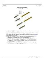
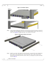
Figure 7: Installation Options
Step 1.
Attach the left and right rack mount rails (A) to the switch, by gently pushing the switch chas-
sis’ pins through the slider key holes, until locking occurs.
Step 2.
Secure the chassis in the rails by screwing 2 flat head Phillips screws (E) in the designated
points with a torque of 1.5±0.2 Nm. See
.
Figure 8: Attaching the Rails to the Chassis
Step 3.
Attach the left and right rack mount brackets (B) to the switch, by gently pushing the switch
chassis’ pins through the slider key holes, until locking occurs. Secure the system in the brack-
ets by screwing the remaining 2 flat head Phillips screws (E) in the designated points with a
torque of 1.5±0.2 Nm. See
Summary of Contents for Spectrum SN2410
Page 72: ...Mellanox Technologies 72 8 9 10 11 12 13...
Page 73: ...Rev 1 2 Mellanox Technologies 73 14 15 16 17 18 19...
Page 75: ...Rev 1 2 Mellanox Technologies 75 3 4 5 6 7 8 9 45 C 113 F 8 3 PSU...
Page 76: ...Mellanox Technologies 76 10 11 12 13 14 15 16 UL 4mA...
Page 78: ...Mellanox Technologies 78 23 24 China CCC Warning Statement TN IT...
Page 91: ...Rev 1 2 Mellanox Technologies 91 7 8 9 10 11 12 13...


