Installation
Rev 1.2
Mellanox Technologies
34
2.5.1.4 SN2410 Splitting Options
Figure 31: SN2410 Splitting Options
2.6
Initial Power On
Each system’s input voltage is specified in the
chapter. The power cords should
be standard 3-wire AC power cords including a safety ground and rated for 15A or higher.
Step 1.
Plug in the first power cable.
Step 2.
Plug in the second power cable.
Step 3.
Wait for the system upload process.
Step 4.
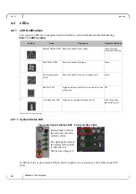
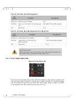
Check the System Status LEDs and confirm that all of the LEDs show status lights consistent
with normal operation (initially flashing, and then moving to a steady color) as shown in
Figure 32 below. For more information, refer to
The system platform will automatically power on when AC power is applied. There is
no power system. Check all boards, power supplies, and fan tray modules for proper
insertion before plugging in a power cable.
It may take up to five minutes to turn on the system. If the System Status LED shows
red after five minutes, unplug the system and call your Mellanox representative for
assistance.
The top QSFP28 ports - 49,51,53,55 (green) are splittable to 4 SFP28 ports each.
All QSFP28 ports can be split into two SFP28 ports.
The bottom QSFP28 ports - 50,52,54,56 (gray) are blocked when the upper ports are in split
mode.
Summary of Contents for Spectrum SN2410
Page 72: ...Mellanox Technologies 72 8 9 10 11 12 13...
Page 73: ...Rev 1 2 Mellanox Technologies 73 14 15 16 17 18 19...
Page 75: ...Rev 1 2 Mellanox Technologies 75 3 4 5 6 7 8 9 45 C 113 F 8 3 PSU...
Page 76: ...Mellanox Technologies 76 10 11 12 13 14 15 16 UL 4mA...
Page 78: ...Mellanox Technologies 78 23 24 China CCC Warning Statement TN IT...
Page 91: ...Rev 1 2 Mellanox Technologies 91 7 8 9 10 11 12 13...


