ESPAÑOL
ES
EN
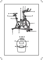
Control panel
M – Mode button
O – Speed indicator
N – Time indicator
P – Distance indicator
S – Pulse indicator
T – Clear button
Q – Calories indicator
R – Scan function
Description
A – Seat
C – Seat height regulator knob
B – Seat regulator knob
D – Bottle holder
E – Intensity regulator knob
F – Pulsation sensor
H – Handlebar height regulator knob
G – Handlebar
I – Flywheel
J – Adjustable feet
K – Pedals
L – Wheels
If the model of your appliance does
not have the accessories described
above, they can also be bought
separately from the Technical
Assistance Service.
ASSEMBLING INSTRUCTIONS:
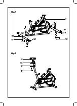
Fig.1
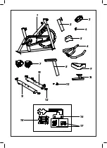
Place the end caps (12) into the front
and rear stabilizers (10,11).
Place the front stabilizer (10) to the
main frame (1) using the screws (15)
–
–
Place the rear stabilizer (11) to the main
frame (1) using the screws (15) provided.
–
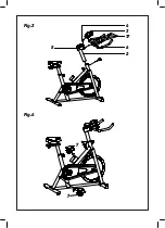
Fig.4
Fix the pedals (7) into its crank arm.
Failure to follow the instructions can
R, screws onto the right-hand crank, also
marked with R, in clockwise direction till
–
–
damage the crank or the pedal threads
The right-hand pedal, marked with letter
–
–
tight.
The left-hand pedal, marked with letter
Fig.3
Fix the handlebar (6) with the handlebar
post (2) with the screws provided (17).
frame (1) and fix it with the handlebar
height adjuster.
–
–
Place the piece (5) as indicated.
Place the handlebar post on the main
–
–
Place the monitor (3) with the bracket
(4) and then fix it to the handlebar (6).
Fig.2
Fix the seat (9) to the seat post (14).
Slide the seat post (14) into the vertical
Insert the vertical seat post (8) into the
main frame (1). Secure the saddle in
–
seat post (8) and fix it in the desired
place with the locking knob (13).
–
–
position with the seat height regulator
knob. The height of the seat can be
adjusted after the bike is fully
assembled.
provided.
L, screws onto the left-hand crank, also
marked with L, in a counter-clockwise
direction till tight.


