User guide
Wireless remote control M-WRG-FBH
- 12 -
Meltem Wärmerückgewinnung GmbH & Co. KG
Am Hartholz 4 · D-82239 Alling
info@meltem.com · www.meltem.com
VENTILATION THE RIGHT WAY
V E N T I L A T I O N & H E A T R E C O V E R Y
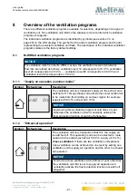
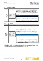
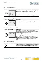
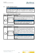
5.2
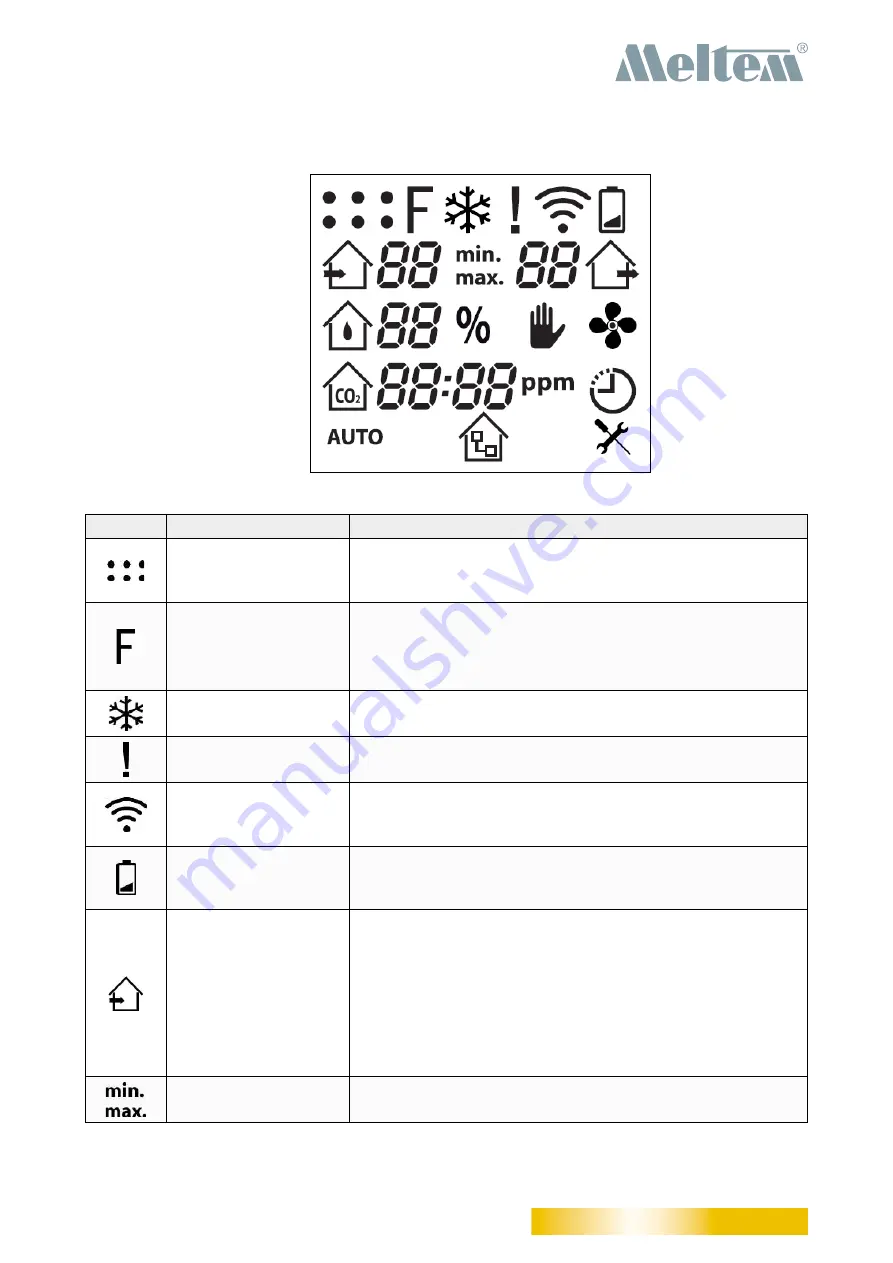
Symbols on the LCD display
Fig. 3:
Symbols on the LCD display
Symbol Name
Description
Ventilation units
One dot is displayed for every ventilation unit that is
connected (up to 6). The flashing dot corresponds to the
ventilation unit with which communication is currently active.
Filter
—
The symbol is displayed continuously if the air filter is
dirty (see section 12 on page 43).
—
The symbol flashes if the one-year filter change interval
is exceeded (see section 12 on page 43).
Frost protection
The symbol appears when the frost protection function is
active.
Exclamation mark
The symbol appears when the ventilation unit signals an
error (see section 12 on page 43).
RF communication
The symbol appears when the remote control is connected
to a ventilation unit and when communication is in progress
with that ventilation unit.
Battery
The symbol appears when the batteries in the wireless
remote control are almost flat and need to be changed (see
section 6.1 on page 14).
Supply air
— Symbol for the “Supply air operation (Summer mode)”
ventilation program. Flashes when activated.
— The value beside the symbol indicates the current supply
air ventilation level in all ventilation programs.
For ventilation units from the
M-WRG-II
series, ventilation
levels with values between
10 and 99
are displayed.
For ventilation units from the
M-WRG
series, ventilation
levels with values between
1 and 10
are displayed.
Min/Max
The symbol indicates whether a value is a minimum or
maximum.


