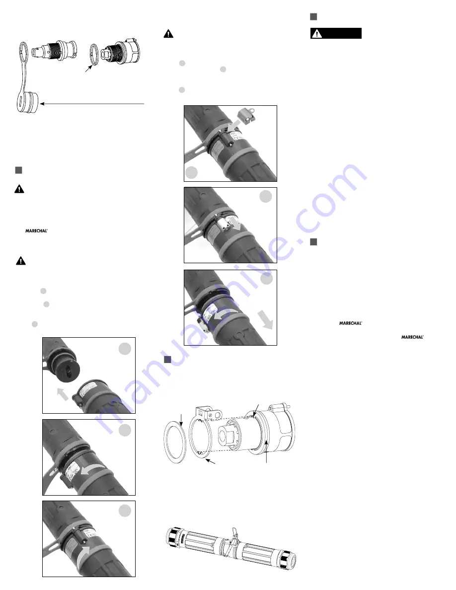
The color-coded rings of receptacles and connectors
include a cap. The color-coded rings of plugs and
inlets do not include a cap.
Rated current and voltage markings
I
t is essential to indicate the current and voltage of
the main circuit on the supplied stickers. Apply the
stickers on or adjacent to the product so they can
easily be seen.
OPERATION
To ensure safe and reliable operation,
MELTRIC plugs and receptacles must be used
in accordance with their assigned ratings.
They can only be used in conjunction with mating
receptacles or plugs manufactured by MELTRIC or
another licensed producer of products bearing
the
technology trademark.
Connection
First check to see that the power source is
de-energized.
DO NOT ENGAGE ON AN
ENERGIZED CIRCUIT
.
Orient the plug so the contact will fit into the recepta-
cle figure 1 . Push the plug partially into the recepta-
cle and rotate the plug counterclockwise until it hits a
stop figure 2 . Then insert plug fully into receptacle
and rotate clockwise about one quarter turn until the
locking pin engages into the slot on the receptacle
figure 3 .
Disconnection
First check to see that the power source is
de-energized.
DO NOT DISCONNECT ON
AN ENERGIZED CIRCUIT
.
Insert unlocking key onto locking pin as shown in
figure 4 . Disengage locking pin by sliding unlocking
key as shown in figure 5 . When locking pin is re-
leased, hold unlocking key in position and twist plug
counterclockwise about 30° as shown in
figure 6 . After turning, withdraw plug.
PADLOCKING OPTION
Assembly
Place the locking ring as shown:
Operation
Connect the product equipped with the locking ring,
insert the shaft and padlock it.
MAINTENANCE
Before inspecting, repairing,
or maintaining MELTRIC
products,disconnect electrical
power to the receptacle to eliminate the risk of elec-
trical shock.
MELTRIC products require little on-going mainte-
nance. However, it is a good practice to periodically
perform the following general inspections:
• Check the mounting screws for tightness.
• Verify that the weight of the cable is supported
by the strain relief mechanism and not by the ter-
minal connections.
• Check the IP gaskets for wear and resiliency.
Replace as required.
• Verify the electrical continuity of the ground circuit.
• Check the contact surfaces for cleanliness
and pitting.
Deposits of dust or similar foreign materials can be
rubbed off the contacts with a clean cloth. Sprays
should not be used, as they tend to collect dirt. If
any significant pitting of the contacts or other serious
damage is observed, the device should be replaced.
Receptacle contacts may be inspected by a qualified
electrician. This should only be done with the power off.
MANUFACTURER’S RESPONSIBILITY
MELTRIC’s responsibility is strictly limited to the
repair or replacement of any product that does not
conform to the warranty specified in the purchase
contract. MELTRIC shall not be liable for any pen-
alties or consequential damages associated with the
loss of production, work, profit or any financial loss
incurred by the customer.
MELTRIC Corporation shall not be held liable when
its products are used in conjunction with products not
bearing the
technology trademark. The use
of MELTRIC products in conjunction with mating
devices that are not marked with the
technology trademark shall void all warranties on
the product.
MELTRIC Corporation is an ISO 9001 certified com-
pany. Its products are designed, manufactured and
rated in accordance with applicable UL, CSA and IEC
standards. MELTRIC designs and manufactures its
products in accordance with Marechal keying standards
established to ensure intermateablility with similarly
rated products manufactured by Marechal Electric
Group.
INSCS1000 G
5
4
6
3
2
1
Insert
Twist then
insert
Twist until
pin locks
Retract
locking
pin
Twist &
Remove
Insert
unlock
tool
Color-coded ring
Watertightness
gasket
Lug
Locking ring
WARNING
DANGER
CAUTION
NOTICE
ADVERTENCIA
DANGER
CAUTION
AVISO
WARNING
DANGER
CAUTION
NOTICE
ADVERTENCIA
DANGER
CAUTION
AVISO
WARNING
DANGER
CAUTION
NOTICE
ADVERTENCIA
DANGER
CAUTION
AVISO
WARNING
DANGER
CAUTION
NOTICE
ADVERTENCIA
DANGER
CAUTION
AVISO
Color-coded ring on plug side
Cap with color-coded ring on receptacle side


