GENERAL
SP devices are single-pole, high-amperage plugs and
receptacles that are designed for safety, durability,
and ease of operation. Each device is mechanically
interlocked with an integral pilot circuit switch for
controlling the power circuit in order to prevent
connection and disconnection under load. Each of
the phases as well as the neutral and ground, are
color coded and keyed to prevent improper connection.
SP receptacles are IP 2X rated to prevent accidental
finger contact with live parts.
There are inherent dangers
associated with electrical
products. Failure to follow
safety precautions can result in serious injury or death.
These instructions must be followed to ensure the safe
and proper installation, operation and maintenance of
the MELTRIC devices. Before installation, disconnect
all sources of power to the circuit to eliminate the risk
of electrical shock. This product must be installed with
an electrical interlock that prevents connection or
disconnection in a loaded condition.
RATINGS
The SP series is CSA listed for use in Non-Load Break
applications up to 600A at 600VAC, 500 HP 3 phase
at 480 VAC and 600 VAC. The SP devices are
NOT designed or listed for current interruption. The
SP receptacle is provided with two auxiliary/pilot
contacts that make (close) when the locking collar
is rotated after plug insertion. The pilot contacts are
designed for use in control circuit wiring of medium
current switchgear, (see diagram of pilot circuit wiring).
The SP pilots have a D300 rating as shown in Table 1.
The phase contact is rated to withstand a 30 kA short
circuit with a current limiting fuse rating as shown in
Table 2. Consult MELTRIC Engineering for horsepow-
er ratings and limitations at lower voltages.
INSTALLATION
SP devices should be installed by qualified
electricians in accordance with all applicable
local and national electrical codes.
Before installing, verify the power is off and the prod-
uct ratings are appropriate for the application. Ensure
the conductors meet code requirements and are with-
in the wiring terminal capacities noted in Table 3.
NOTICE:
Ensure the plug and its flexible cable do
not exert a significant force or a constraint on the
receptacle.
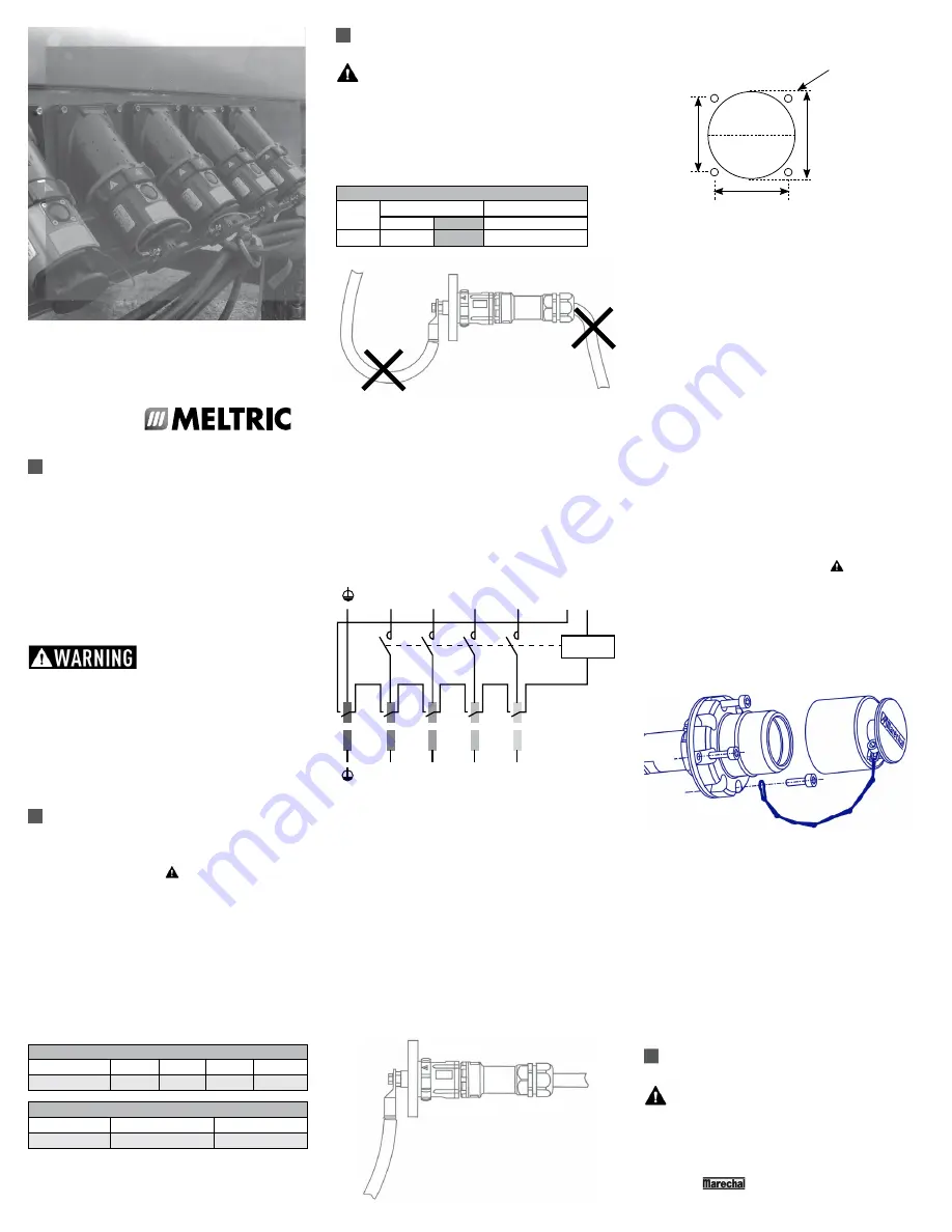
Wiring of the pilot contacts
The SP auxiliary/pilot contact leads of each device
should be wired in series within the power control
circuit. A typical pilot circuit wiring diagram is
shown below.
Wiring of the main conductor
Use a flexible cable between 2/0 and 777 MCM (70
and 400 mm
2
). Strip the insulation as appropriate for
the lug being used. Solder lugs have integral threads
that screw into the terminals. The solder lug should
be tightened until the tapered section is secured in
solid contact with the terminal. Crimped lugs are
secured with M12 bolts that should be tightened to
approximately 30 ft-lb (40 N.m.) with a 3/4" (19 mm)
wrench.
NOTICE:
To avoid transmitting torque to the device
moldings when securing the lugs, hold the terminal in
place with a 24 mm wrench (flats are provided).
Hole Pattern for Custom Mounting
NOTICE:
In order to maintain IP66/67 protection in
custom installations, watertight seals must be used
under the heads of the four mounting bolts and they
must be retained by a lock washer and nut on the
inside of the box or panel. Alternatively, four blind
holes can be drilled and threaded to accommodate
#8-32 x 5/8" mounting screws. The hole depth must
be sufficient to achieve adequate gasket compression.
Attaching the handle
Insert cable through cable gland and handle before
tightening the phase conductor. Assemble handle
with the screws and gasket supplied, (use short
screws for inlets, long screws for receptacles) and
tighten cable gland with an appropriate tool.
NOTICE:
MELTRIC solder lugs are required for use
with handles.
Attaching the metal angle (if required)
Attach receptacle or inlet to metal angle using the
screws and gasket supplied, (use short screws for
inlets, long screws for receptacles). Connect the
metal angle to ground.
Assembly of the plug/inlet cap
Attach the cap to the plug/inlet by retaining the end
of the chain under one of the mounting screws.
Gasket
In order to achieve rated watertightness, the flat
black gasket must be installed between the inlet or
receptacle and the panel or accessory to which it
is attached.
Rated current and voltage markings
It is essential to indicate the current and voltage of
the main circuit on the supplied stickers. Apply the
stickers on or adjacent to the product so they can
easily be seen.
OPERATION
To ensure safe and reliable operation,
MELTRIC plugs and receptacles must be used
in accordance with their assigned ratings.
SP devices can only be used in conjunction with
mating receptacles or plugs manufactured by
MELTRIC or another licensed producer of products
bearing the
™
technology trademark.
L1
L2
L3
N
L1
L2
L3
N
P1
P2
L1
L2
L3
N
L1
L2
L3
N
P1
P2
2"
1.67"
1.67"
Ø.201 thru or
tap for 10-32
Table 1 - Auxiliary Contact Ratings
Device
120VAC 240VAC 480VAC 600VAC
SP
.6A
.3A
–
–
Table 2 - Short Circuit Withstand Ratings
Device
Rating Fuse
Type
1
SP – 600A
30 kA @ 600 VAC
Class L 1400A
2
1 - Short Circuit Rating applies with fusing up to this amperage.
Ratings are based on tests performed with Ferraz Shawmut non-
time Delay Current Limiting fuses.
2 - Tests performed with maximum allowable motor fusing sized per
the 2008 NEC.
Max
Min
SP
777 MCM
2/0
12-14 AWG
Table 3 - Wiring Terminal Capacity
Main Contacts
Aux. Contacts
SP
OPERATING INSTRUCTIONS
A company of MARECHAL ELECTRIC GROUP
MELTRIC Corporation
/ 4765 W. Oakwood Park Drive Franklin, WI 53132
Tel. : 800 433 7642 / Fax : 414 433 2701 / e-mail : mail@meltric.com
INSSP F
A manufacturer of products using
Marechal technology
meltric
.com


