background image

Installation Manual: MEMC Silvantis 60 cell PV Modules

11 of 15

© Copyright 2012 MEMC Electronic Material

7.0 MEChAnICAL And ELECTrICAL PArAMETErS And SPECIfICATIonS

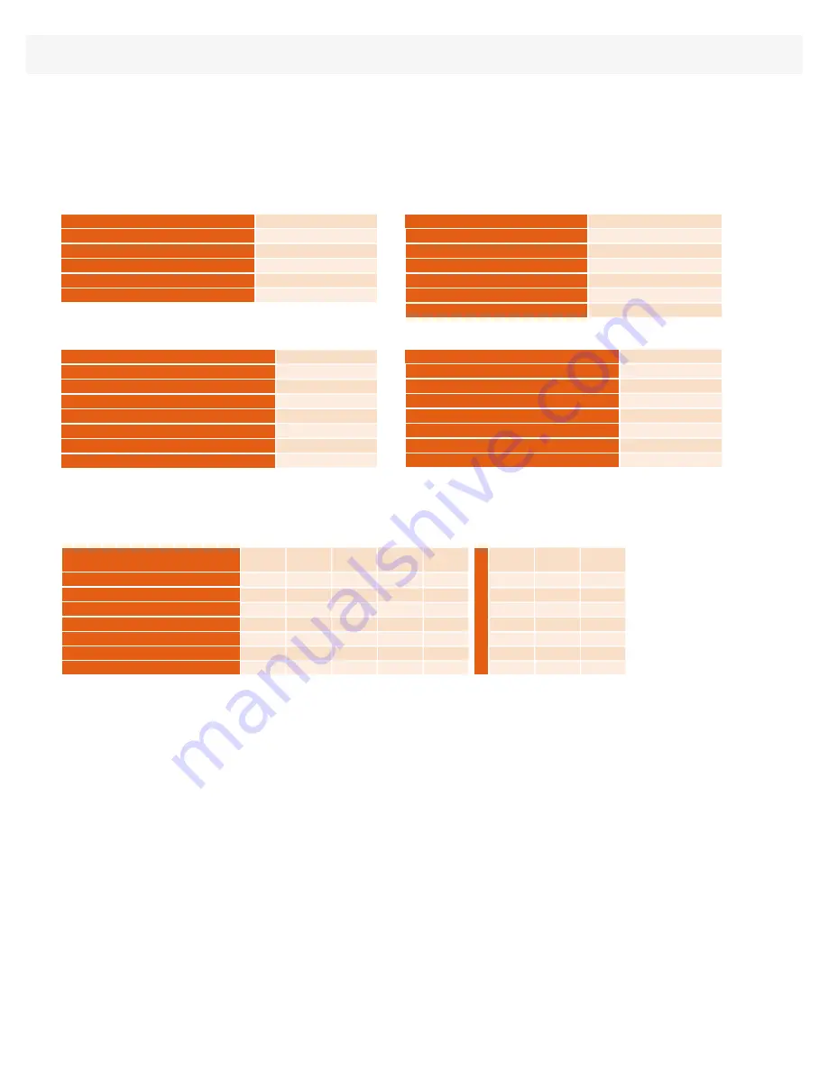
Modules with tempered glass:  
MEMC-M235/240/245/250/255AMA  

Modules with corner cap and tempered glass:  
MEMC-M240/250/260LMA

Module dimensions (mm)
Module weight (kg)
Cell-Type
number of Cells
frame Material
glass (mm)

1,658 x 990 x 50
19
Mono-crystalline
60
Anodized Aluminum
3.2 Tempered glass

PhySICAL PArAMETErS

nominal operating Cell Temperature (noCT) (°C)
Temperature Coefficient of P

max  

(%/°C)*

Temperature Coefficient of v

oc  

(%/°C)*

Temperature Coefficient of I

sc  

(%/°C)* 

operating Temperature (°C)
Maximum System voltage (v)  
Limiting reverse Current (A)
Maximum Series fuse rating (A)

46±2
-0.47 to -0.49
-0.35
+0.036 to +0.055
-40 to +85
600 (uL) 

&

 1000 (IEC)

8.40
15

TEMPErATurE CoEffICIEnTS And PArAMETErS

*

Temperature coefficients may vary by ± 10%
*refer 240w solar module and MEMC Silvantis 250w module data sheets for specific 

temperature coefficients

nominal operating Cell Temperature (noCT) (°C)
Temperature Coefficient of P

max  

(%/°C)*

Temperature Coefficient of v

oc  

(%/°C)*

Temperature Coefficient of I

sc  

(%/°C)*

operating Temperature (°C)
Maximum System voltage (v)
Limiting reverse Current (A)
Maximum Series fuse rating (A)

46  ±2
-0.47 to -0.49
-0.35
+0.036 to +0.055
-40 to +85
600 (uL) 

&

 1000 (IEC)

8.40
15

TEMPErATurE CoEffICIEnTS And PArAMETErS

*

Module dimensions (mm)
Module weight (kg)
Cell-Type
number of Cells
frame Material
Corner Caps
glass (mm)

1,674 x 1,006 x 50
19.3
Mono-crystalline
60
Black Anodized Aluminum
Black Anodized Aluminum 
3.2 Tempered glass

PhySICAL PArAMETErS

All electrical data at STC: 1000w/m

2

, AM1.5, 25ºC

Electrical characteristics may vary by ±5% 

Model #
rated Maximum Power Pmax (w)
open-Circuit voltage v

oc

 (v)

Short Circuit Current I

sc  

(A)

Module Efficiency (%)
Maximum Power Point voltage v

mpp 

(v)

Maximum Power Point Current I

mpp

 (A)

Power range (w)

MEMC- 
M235AMA

235
37.3 
8.60
14.3
29.3
8.03
-0/+5

MEMC- 
M240AMA

240
37.4 
8.70
14.6
29.5
8.15
-0/+5

MEMC- 
M245AMA

245
37.5 
8.80
14.9
29.7
8.25
-0/+5

ELECTrICAL ChArACTErISTICS

*

MEMC- 
M240LMA

240
37.4
8.70
14.6
29.5
8.15 
±6

MEMC- 
M250LMA 

250 
37.6
8.90
15.2
29.9
8.36
-4/+5

MEMC- 
M250AMA

250
37.6
8.90
15.2
29.9
8.36
-0/+5

MEMC- 
M255AMA

255
37.8
9.00
15.5
30.0
8.50
-0/+5

MEMC- 
M260LMA 

260 
38.0
9.10
15.8
30.1
8.64
±5

M

odules with c

or

ner caps

Temperature coefficients may vary by ± 10%
*refer 240w solar module and MEMC Silvantis 250w module data sheets for specific 

temperature coefficients

* Listed specifications are subject to change without prior notice.

Summary of Contents for SunEdison MEMC-M235AMA

Page 1: ...A MEMC M240AMA MEMC M245AMA MEMC M250AMA MEMC M255AMA MEMC M240LMA MEMC M250LMA MEMC M260LMA MEMC M240AMC MEMC M245AMC MEMC M250AMC MEMC M255AMC MEMC M260AMC MEMC M240LMC MEMC M250LMC MEMC M260LMC Ins...

Page 2: ...tallation using shared rails M240 250 260LMA and M240 250 260LMC 7 4 5 Mechanical Installation Warnings 8 5 0 Electrical Installation 8 5 1 Planning and Design 8 5 2 Module Wiring 8 5 3 Grounding 9 5...

Page 3: ...vantis Photovoltaic modules consist of a series of electrically interconnected crystalline silicon solar cells that are sealed within a laminated sheet of tempered glass superstrate and EVA back sheet...

Page 4: ...cing which may result in burns fires or other problems Follow industry best practices when commissioning trouble shooting disconnecting or connecting a PV system Trouble shooting should include planni...

Page 5: ...ations For mounting locations for clamps or bolt for specified load please refer to Table on page 6 Each module should be mounted using four bolts through the mounting holes on the rear side of the mo...

Page 6: ...oles on each long side frame NOTE All modules are rated for a maximum rear load of 2400 Pa and a maximum front load of 5400 Pa when fixed to the mounting holes on the long side frames only Structural...

Page 7: ...260LMC SPECIFIC Toe in Modules using Corner Cap Feature System Overview Installation Step Illustration Toeing module into rail hook Module clip attachment Step 1 Place the bottom of the module on the...

Page 8: ...ately sized for the system design according to national regional and local codes Electrical characteristics are within plus or minus 5 of rated values for Isc Voc Impp and Vmpp Modules may operate und...

Page 9: ...um short circuit current of the system maximum operating temperatures and cable run lengths For field connections use at a minimum 12 AWG 4 mm2 wires insulated for a minimum of 85 C Use copper wire on...

Page 10: ...erience and is believed to be accurate However all information in this manual without exception including recommendations and specifications does not constitute a warranty expressed or implied MEMC re...

Page 11: ...ure C Maximum System Voltage V Limiting Reverse Current A Maximum Series Fuse Rating A 46 2 0 47 to 0 49 0 35 0 036 to 0 055 40 to 85 600 UL 1000 IEC 8 40 15 TEMPERATURE COEFFICIENTS AND PARAMETERS Mo...

Page 12: ...46 2 0 49 0 35 0 055 40 to 85 600 UL 1000 IEC 8 40 15 TEMPERATURE COEFFICIENTS AND PARAMETERS Module Dimensions mm Module Weight kg Cell Type Number of Cells Frame Material Corner Caps Glass mm 1 674...

Page 13: ...al 8 0 Appendix 8 1 Module dETAILS A 990 39 0 B 1 658 65 3 C 50 2 0 D 40 1 6 E 940 37 0 F 1 608 63 3 G 994 39 1 H 594 23 4 Module Dimensions Mounting Hole Spacing Dimension MM INCH Dimension MM INCH L...

Page 14: ...PV Modules 14 of 15 Copyright 2012 MEMC Electronic Material Front View Bolt Stack Details Center Mount Option 8 0 Appendix 8 1A Module dETAILS M240 250 260LMA and M240 250 260LMC SPECIFIC dimensions...

Page 15: ...tch printed version to documentation database MEMC Electronic Materials Inc 501 Pearl Drive City of O Fallon St Peters MO 63376 USA 1 636 474 5000 www sunedison com 8 0 AppendiX 8 3 Pre mounted Cables...

Reviews: