Installation Manual: MEMC Silvantis 60 cell PV Modules
7 of 15
© Copyright 2012 MEMC Electronic Material
4.3 ModuLE InSTALLATIon uSIng CEnTEr MounTIng BrACkETS
• Modules may also be mounted using center clamps as shown in Appendix 8.2, for use with trackers.
• Module clamps for center mounting must be based on MEMC approved extrusion and hardware.
• for module loads higher than 2400 Pa, module clamps and hardware must be pre-approved by MEMC.
4.4 ModuLE InSTALLATIon uSIng ShArEd rAILS (M240/250/260LMA And M240/250/260LMC SPECIfIC)
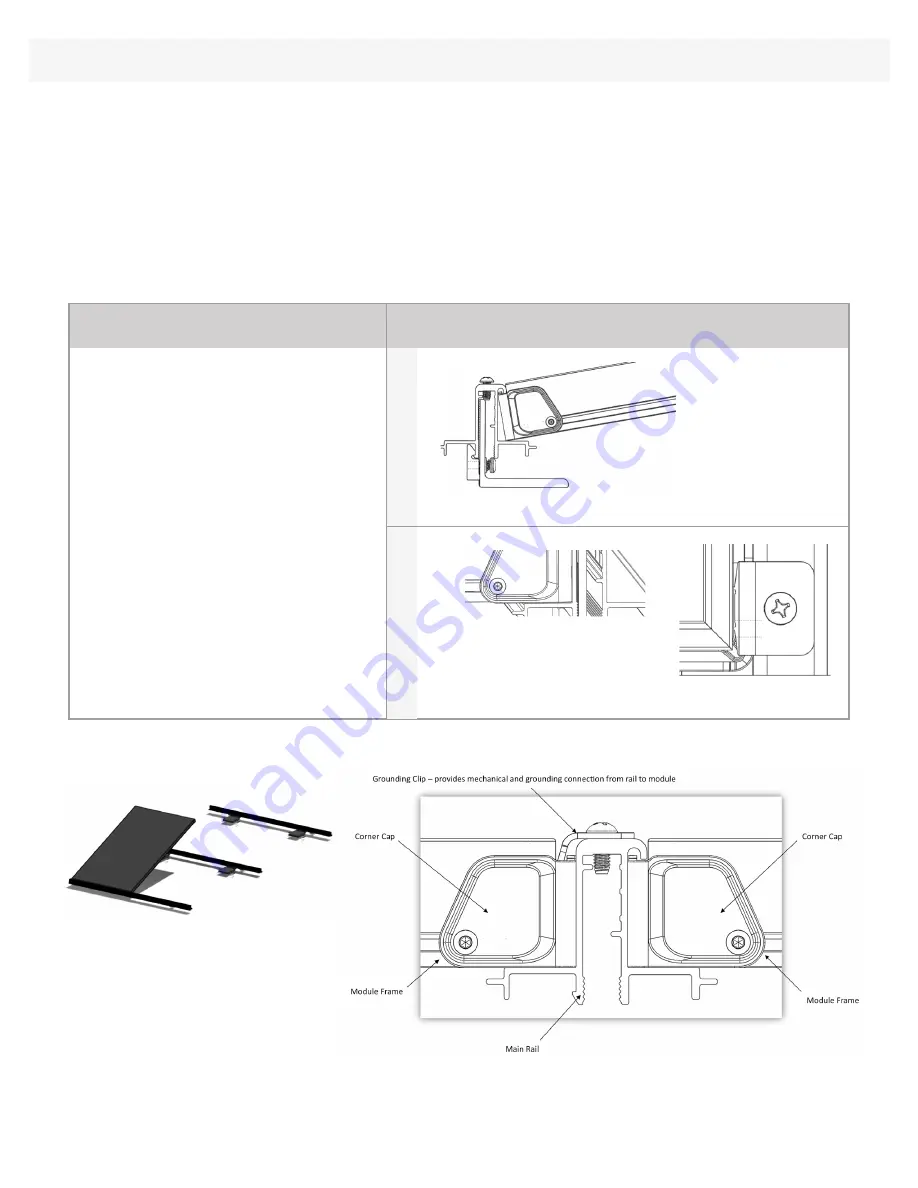
Toe in Modules using Corner Cap feature
System overview
InSTALLATIon STEP
ILLuSTrATIon
Toeing module into rail hook
Module clip attachment
Step 1:
Place the bottom of the module on the
approved rail at an angle, allowing the module
to toe into the rail hook as shown in figure to the
right, and lower onto the ledge of the next rail.
Step 2:
Ensure that the rails are tight against
the modules by adjusting the upper rail.
Step 3:
use the module clips provided to clamp
the module to the rail at each of the two upper
corners on the module frame as shown in figure
to the right.
Step 4:
Tighten the included fasteners for the
clips to 11.5 newton.meters (or 8.5 foot pounds
of torque).
STEP
3
STEP
1


