DISASSEMBLY INSTRUCTIONS
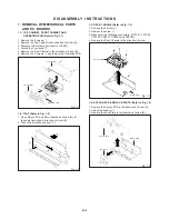
1. REMOVAL OF MECHANICAL PARTS
AND P.C. BOARDS
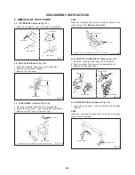
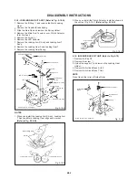
1-1: TOP CABINET, FRONT CABINET AND
OPERATION PCB (Refer to Fig. 1-1)
1.
2.
3.
4.
5.
6.
Remove the 4 screws
1
.
Remove the Top Cabinet in the direction of arrow (A).
Disconnect the following connector: (CP651).
Unlock the 7 supports
2
.
Remove the Front Cabinet in the direction of arrow (B).
Remove the 3 screws
3
and remove the Operation PCB.
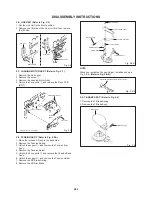
1-3: DECK CHASSIS (Refer to Fig. 1-3)
Remove the 3 screws
1
.
Remove the screw
2
.
Disconnect the following connectors: (CP1001, CP1002,
CP1003, CP4001, CP4002 and CP4003).
Remove the Deck Chassis in the direction of arrow.
1.
2.
3.
4.
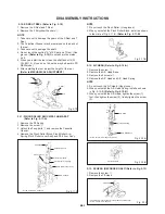
1-4: SYSCON PCB AND JACK PLATE (Refer to Fig. 1-4)
1.
2.
3.
B1-1
Deck Chassis
Fig. 1-3
1
1
1
Remove the Syscon PCB in the direction of arrow (A).
Unlock the support
1
.
Remove the Jack Plate in the direction of arrow (B).
Fig. 1-1
Top Cabinet
3
1
(A)
Front Cabinet
(B)
3
3
Operation PCB
2
2
2
2
2
2
1-2: FLAP (Refer to Fig. 1-2)
1.
2.
Open Flap to 90˚ and flex in direction of arrow (A), at
the same time slide in direction of arrow (B).
Then lift in direction of arrow (C).
(A)
(C)
(B)
Flap
Fig. 1-2
2
1
1
1
2
Bottom Plate
Fig. 1-4
Syscon PCB
Jack Plate
(A)
(B)
1
Bottom Plate
Summary of Contents for MVR4041
Page 51: ...M4E4 04B K124004 SPEC NO O R NO...
Page 101: ...M4F2 04B O R NO SPEC NO K1X4011...
Page 152: ...K214008 O R NO M4F2 23B SPEC NO...
Page 157: ...M4F2 04B K1Z4014 SPEC NO O R NO...


