DISASSEMBLY INSTRUCTIONS
B2-5
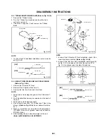
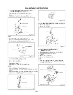
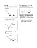
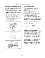
Fig. 2-15-A
NOTE
In case of the Pinch Roller Cam and Main Cam
installation, install them as the circled section of Fig. 2-
15-B so that the each markers are met. (Refer to Fig.
2-15-B)
2-15:
Remove the E-Ring (1), then remove the Main Cam.
Remove the E-Ring (2), then remove the Pinch Roller
Cam and Joint Gear.
1.
2.
MAIN CAM/PINCH ROLLER CAM/JOINT GEAR
(Refer to Fig. 2-15-A)
Main Cam
Pinch Roller Cam
Joint Gear
1.
Pinch Roller Cam
Main Cam
Marker
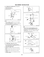
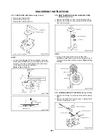
2-16: LOADING GEAR S/T UNIT (Refer to Fig. 2-16-A)
1.
2.
Remove the E-Ring (1) and remove the Main Loading
Gear.
Remove the Main Rod, Tension Lever, Loading Arm S
Unit and Loading Arm T Unit.
Main Rod
Main Loading Gear
Loading Arm T Unit
Loading Arm S Unit
Fig. 2-16-A
(1)
(1)
(2)
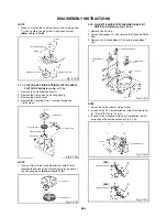
2-14: CAPSTAN DD UNIT (Refer to Fig. 2-14-A)
Remove the Capstan Belt.
Remove the 3 screws (1).
Remove the Capstan DD Unit.
1.
2.
3.
Fig. 2-14-A
€ Screw Torque: 4 ± 0.5kgf€cm
Capstan DD Unit
Capstan Belt
(1)
(1)
(1)
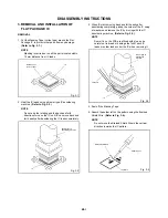
In case of the Capstan DD Unit installation, apply the
silicon bond (TSE3843-W) on the position Fig. 2-14-B
correctly. )if no silicon bond applied, abnormal nosie
will be heard on the deck operation.)
(Refer to Fig. 2-14-B, C)
NOTE
1.
Fig. 2-15-B
Fig. 2-14-B
Fig. 2-14-C
Tension Lever
Main Chassis
Silicon Bond
Capstan DD Unit
Applied position of
silicon bond
Be careful not to apply the silicon
bond to the Pinch Roller.
Summary of Contents for MVR4041
Page 51: ...M4E4 04B K124004 SPEC NO O R NO...
Page 101: ...M4F2 04B O R NO SPEC NO K1X4011...
Page 152: ...K214008 O R NO M4F2 23B SPEC NO...
Page 157: ...M4F2 04B K1Z4014 SPEC NO O R NO...


