Read and perform this adjustment when repairing the
circuits or replacing electrical parts or PCB assemblies.
ELECTRICAL ADJUSTMENTS
1. BASIC ADJUSTMENT
CAUTION
When replacing IC's or transistor, use only specified
silicon grease (YG260M).
(To prevent the damage to IC's and transistors.)
1-1: PG SHIFTER
CONDITIONS
MODE-PLAYBACK
Input Signal-Alignment Tape (JG001P)
INSTRUCTIONS
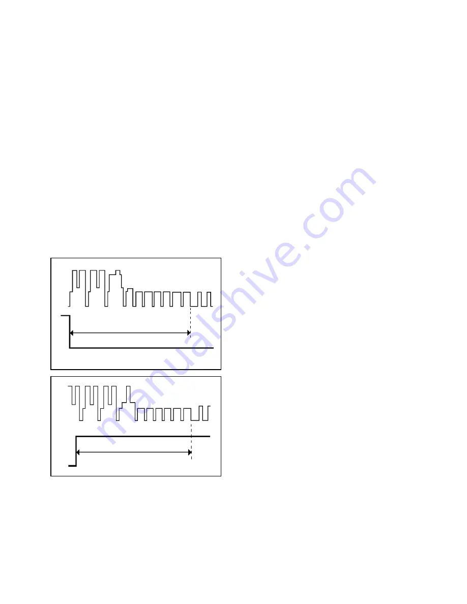
Connect CH-1 on the oscilloscope to TP1002 and CH-2
to TP4201.
Playback the alignment tape. (JG001P)
Press and hold the Tracking-Auto button on the remote
control more than 2 seconds to set tracking to center.
Adjust the VR1001 until the waveform of the oscilloscope
measures 6.5
±
0.5(H) at both leading and trailing edges.
(Refer to Fig. 1-1-A, B)
1.
2.
3.
4.
6.5H
CH-1
CH-2
Fig. 1-1-A
CH-1
CH-2
6.5H
Fig. 1-1-B
D3-1


