Product Description
Memotec Inc.
5-5
NOTE:
To turn the
ALARM
LED off, enter the
CE
(Clear ERR/DIAG LED) com-
mand at the console command line.
Rear Panel
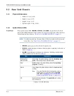
As mentioned in the preceding section, the rear panel also includes a set of system status
LEDs, below Slot 1. These LEDS (
POWER
,
STATUS
and
ALARM
) duplicate the front
panel system status LEDs. See
“System Status LEDs” on page 5-4
Green
The
application
is running and at least one link is up
State
Interpretation
Blinking Red/
Amber/Green
Early stage of system startup, when the bootstrap is
executing a quick hardware test
Red
A software reset has occurred
a
a.
Amber
A
Write
operation to Flash memory is in progress, e.g.
while saving the application after a download
Green
Hardware initialization is in progress
Off
No alarm has occurred on the unit since the alarms
were last cleared
Table 5-5: ALARM LED states
State
Interpretation
Table 5-4: STATUS LED states
Summary of Contents for NetPerformer SDM-9220 Series
Page 1: ...NetPerformer SDM 9220 SDM 9230 Hardware Installation Guide ...
Page 8: ...Memotec Inc ...
Page 12: ...Memotec Inc ...
Page 13: ...1 Memotec Inc 1 1 Preface ...
Page 24: ...SDM 9220 9230 Hardware Installation Guide 1 12 Memotec Inc ...
Page 25: ...2 Memotec Inc 2 1 Compliance Information ...
Page 39: ...Compliance Information Memotec Inc 2 15 2 3 3 Compliance to China RoHS ...
Page 41: ...3 Memotec Inc 3 1 Unpacking ...
Page 47: ...4 Memotec Inc 4 1 Hardware Installation ...
Page 80: ...SDM 9220 9230 Hardware Installation Guide 4 34 Memotec Inc ...
Page 81: ...5 Memotec Inc 5 1 Product Description ...
Page 113: ...6 Memotec Inc 6 1 Serial Port and User Equipment Connections ...
Page 122: ...SDM 9220 9230 Hardware Installation Guide 6 10 Memotec Inc ...
Page 123: ...7 Memotec Inc 7 1 Networking Features ...
Page 127: ...8 Memotec Inc 8 1 Troubleshooting Tips ...


