Item #
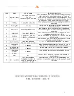
NAME
Wire Identification
DESCRIPTION / INSTRUCTION
1
Auger Motor Wiring
1x Black Wire, 1x White Wire
Snap Disk
Leads Extending from Auger Motor
Attach the white wire shown to one of the leads extending from the auger
motor. Attach the black wire to the snap disk as shown. The 2
nd
lead
extending from the auger motor attaches to the opposite side of the snap
disk as shown. The snap disk is a thermal switch which will cut power to
the auger motor in the event that its critical temperature is reached.
2
RTD Wiring
1x Orange Wire, 1x Brown Wire
Attach both spade connectors to the leads extending from the RTD as
shown above.
3
Grounding Wire
Green Wire
The connection point for the ground is located on the auger motor
gearbox body as shown.
4
Ethernet Cable
Black Cable with Ethernet End
Attach the Ethernet cable to the terminal on the Wi-Fi card as shown.
Ensure that the wiring does not interfere with the auger motor’s moving
components.
5
Igniter Wiring
1x Red Wire, 1x White Wire
Attach both spade connectors to the leads extending from the igniter.
These leads will extend from next to the fan.
6
Fan Wiring
1x Blue Wire w/ 2 spade ends,
1x White Wire w/ 2 spade ends
Attach the connections on this jumper to the two tabs located on the side
of the fan housing.
7
USB Port
N/A
Used to update your grill, see the “Updating Controller
Software” section
of the main manual for information.
8
Meat Probe Wiring
1x Red Wire 1x Black Wire,
Wires twisted around each other
This terminal is used to connect the meat probes to the controller
9
120/240 Select
Jumper
1x Black Wire
Used when chan
ging the input voltage to the controller, see “120v to
240v Conversion” section of the main manual for information.
10
AC Load Wire from
Filter to Controller
1x Black Wire
Carries AC voltage from the filter to the control board, load wire.
11
AC Neutral Wire
from Filter to
Controller
1x White Wire
Carries AC voltage from the filter to the control board, neutral wire.
12
Filter
N/A
Reduces electrical feedback. Line = Outlet Side, Load = Grill Side. L1 =
Load L2= Neutral
13
MOV + Fuse Holder
1x Red Wire 1x White Wire,
Pair is joined in the middle with
black shrink wrap. Fuse holder is
cylindrical and white plastic.
A two wire component which has a ferrite choke to eliminate input
electrical disturbances from the grid. Load and Neutral wires. Fuse holder
that accepts
CONTACT YOUR DEALER OR MEMPHIS GRILLS TECHNICAL SERVICE WITH ANY QUESTIONS.
TECHNICAL SERVICE NUMBER: 1-888-883-2260
012
Summary of Contents for Beale Street BGSS26
Page 11: ...011 ...

