13
Item #
NAME
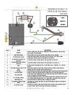
Wire Identification
DESCRIPTION / INSTRUCTION
1
Auger Motor
Wiring
1x Black Wire, 1x White Wire
Attach both spade connectors to their respective terminals on the
top of the auger motor as indicated by the arrows shown above.
2
RTD Wiring
1x Orange Wire, 1x Brown Wire
Attach both spade connectors to the leads extending from the RTD
as shown above.
3
Grounding Wire
Green Wire
The connection point for the ground is located directly below the
auger motor on the vertical panel behind the auger motor.
4
Ethernet Cable
Black Cable with Ethernet End
Attach the Ethernet cable to the terminal on the Wi-Fi card as
shown. Ensure that the wiring does not interfere with the auger
motor’s moving components.
5
Igniter Wiring
1x Red Wire, 1x White Wire
Attach both spade connectors to the leads extending from the
igniter. These leads will extend from the airbox and can be located
in between the two fans.
6
Fan Wiring
1x Blue Wire w/ 2 spade ends,
1x White Wire w/ 2 spade ends
Attach BOTH blue spade connectors to 1 fan and then attach the red
spade connectors to the other fan.
NOTE: ALL TWO WIRE PAIRS FOR A SPECIFIC COMPONENT ARE REVERSABLE
Example: The auger motor wiring can have the either spade connector from
its two wire pair attached to either terminal and the motor will function
normally.
RTD
MEMPHIS ELITE BUILT-IN
COMPONENT WIRING
DIAGRAM
FANS
IGNITER
AUGER
MOTOR
WIFI CARD


