7
Follow the assembly steps listed below, prior
to installation of the unit. The unit can be
supported by either the support brackets
(items 13, 14 & 15) or by the four leveling feet
(item 10). Refer to page 4 for item part
numbers, descriptions and quantities.
Note that the support brackets must be
installed with either support method.
12) Remove the ash/grease drawers from the
unit.
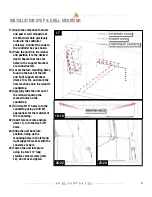
13) Fasten the left and right support brackets
(items 13 and 14) to the unit using the ten
1/4”-20 stainless steel hex bolts (item 5).
14) Fasten the rear support bracket (item 15)
to the left and right support brackets
(items 13 and 14) with two 10-24 x ½”
long stainless steel screws (item 7).
15) This step is only to be done if the grill is
going to be supported by the four leveling
feet (item 10) and not the support
brackets. Thread the four leveling feet
(item 10) into the bottom of the unit.
Optional:
16) To reduce the clearance to combustible
materials, the optional heat shield kit
should be used. Refer to page one to
determine if the heat shield kit is required
for your installation. Follow the assembly
instructions provided with the heat shield
kit to properly fasten the kit to the unit.
INSTALLATION STEP 3: BRACKETS
12-15
16


