MENNEKES AM-TITE PLUG SERIES
WIRING INSTRUCTIONS
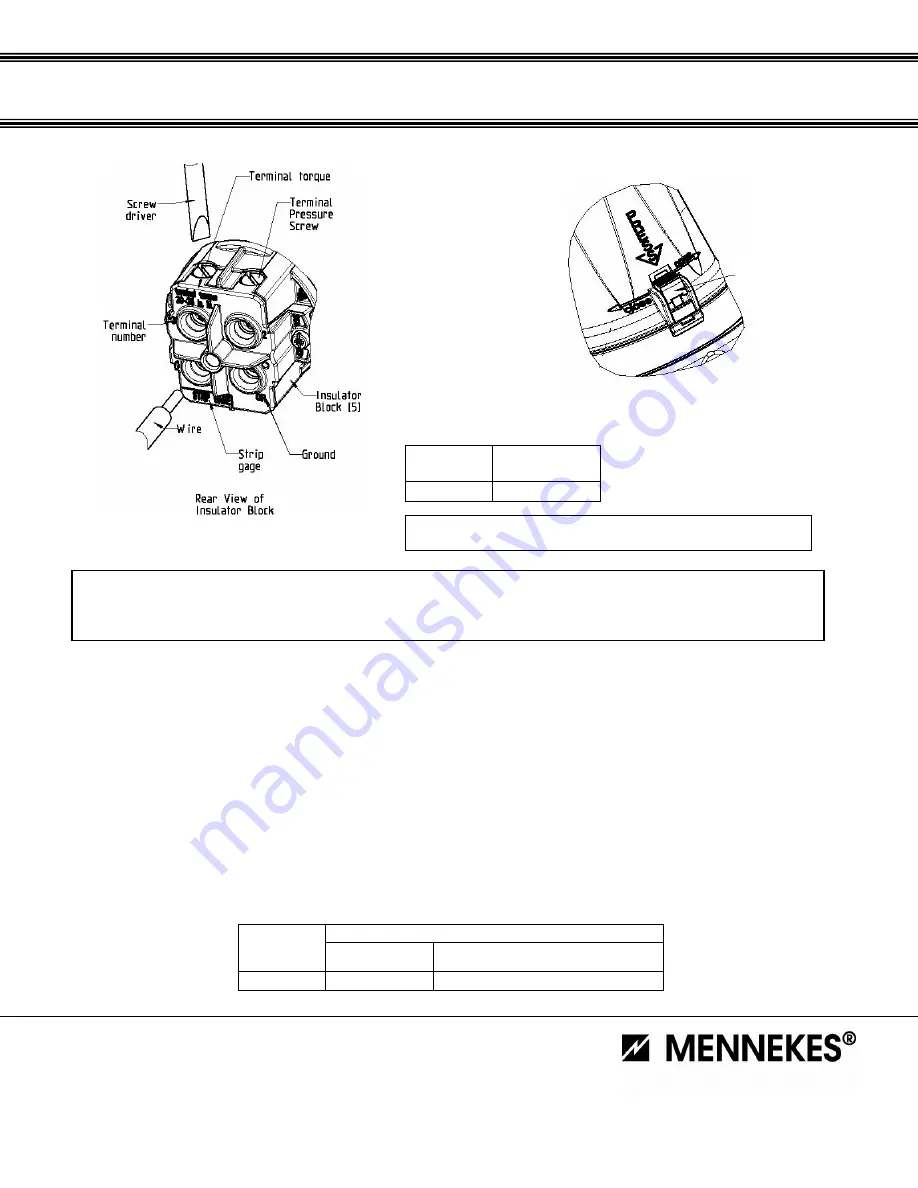
Figure 3
Figure 4
6. Connect wires to proper terminals in insulator block. Back out terminal pressure screws if needed, but do not remove. Insert
conductors including all strands into contact terminals according to the established wiring pattern. Conductors must bottom in
contact terminal well. If stripped according to Table A the conductor insulation should extend below surface of insulator block.
Tighten terminal pressure screws to the torque value listed in Table C. The terminal torque can be found on the insulator block,
see Figure 3.
7. Thread rear housing (1) into front housing and align black locking tab (10) with receiving piece on front housing (2). Pres tab (10)
as arrow directs to secure rear and front housing together.
8. Slide multi-cut grommet (8) and washer (7) into threaded entry of rear housing (1) Screw strain relief (4) into rear housing (1) and
torque per Table D. The torque value is located on the strain relief (4). Secure set screw in place so strain relief cannot turn.
9. Tighten cable clamp screws (11) around power cable to the torque in Table D. Alternate sides as needed to prevent binding.
Copyright 2008 © MENNEKES Electronics, Inc.
Specifications subject to change.
MENNEKES Electrical Products
2 77 Fairfield Road
Fairfield, NJ 07004
8 00-882-7584
www .MENNEKES.com
Table C
Torque values for Terminal Pressure Screws*
Amperes
Rating
Torque (in.lb.)
60
30-35
TABLE D
Torque values for Strain Relief (4) and Cable Clamp Screws(11)
Torque value (in.lb.) for
Amperes
Rating
(4) Strain Relief
Nut
(11) Cable Clamp Screw
60
min. 66
35
*Note:
Each terminal should be torqued at full recommended value for 2 complete
cycles: Tighten each screw in terminal for one cycle and repeat the process
(10) Locking Tab
CAUTION
Apply the next steps with care. Otherwise the plug will not be tight and/or the cable grip will not be correct.
Risk of serious/fatal injuries due to electrocution could occur if steps are not completed properly.


