Operating Instructions - CPC6050
125
Modular Pressure Controller
CPC6050
CPR6050
0019090XXX
9.3 Transducer Removal
Follow the following instructions for transducer removal or replacement:
• VENT THE SYSTEM by placing the controller in vent mode. Then turn off the power.
• Loosen the Philips screws that secure the door.
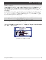
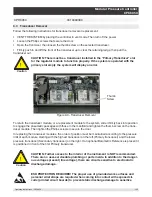
• Open the front door, then loosen the thumb screw on the selected transducer.
• Firmly push in and lift the front of the transducer up to clear the retaining ledge, then pull the
transducer out.
CAUTION: There must be a transducer installed in the “Primary Transducer” slot
for the regulator module to function properly. If the system is operated with the
primary slot empty the system will display an error.
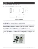
Thumb
Screw
Figure 9.3 - Transducer Removal
To return the transducer module, or a replacement module to the system, slide it firmly back into position
to engage the pneumatic passages with those in the manifold and tighten the thumb screw on the trans-
ducer module. Then tighten the Philips screws to secure the door.
In replacing the transducer modules, the order of position must be maintained according to the pressure
limit of each module, starting with the highest transducer on the left (Primary transducer) and the lower
pressure transducer (Secondary transducer) on the right. If an optional Barometric Reference is present it
is positioned in front of the first Primary transducer.
CAUTION: Further access to the interior of the instrument is NOT recommended.
There are no user-serviceable plumbing or parts inside. In addition to the danger-
ous voltages present (line voltage), there are circuits sensitive to electrostatic
discharge damage.
ESD PROTECTION REQUIRED! The proper use of grounded work surfaces and
personal wrist straps are required when coming into contact with exposed cir-
cuits (printed circuit boards) to prevent static discharge damage to sensitive
!
Caution
!
Caution

