Operating Instructions - CPC6050
25
Modular Pressure Controller
CPC6050
6 Local Operation and Setup
6.1 General Operation
This section describes the procedures for operating the CPC6050 from the front panel. Instructions for
operating the device remotely from an external computer are covered in Section 7, Remote Operation. By
following the procedures provided in these two sections and Section 10, Calibration, you can expect your
CPC6050 to deliver maximum accuracy and dependability for many years of useful service.
6.1.1 Setup Applications
Configuration of the CPC6050 is achieved by changing settings accessed through the Application (“App”)
buttons. Local operation is accomplished by observing the data presented in the display. The appearance
and functionality of the display can be changed by pressing the App button for the related function. After
an app has been chosen, a set of related parameters will appear on the left. After choosing one of these
parameters, a set of selections related to that parameter will appear on the right or a data entry keypad.
The desired selection or data can be entered here.
6.1.2 Display Screen Features
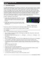
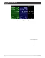
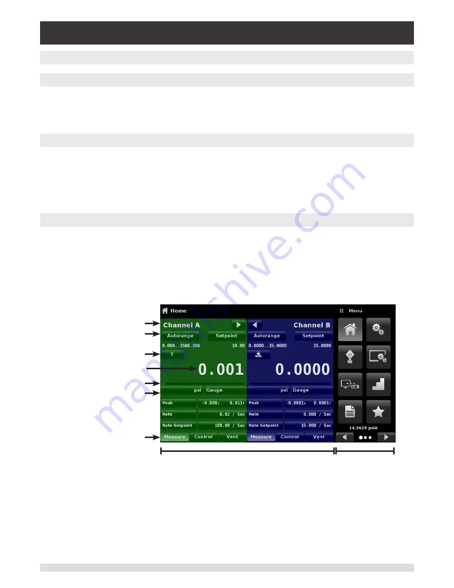
The screen shown below provides an overview of the features that may appear on the display after initial-
ization. The left three fourth of the display contains the area where information is displayed (in this case
the Home Application) and the right one fourth contains the selection icons for each application. A zero
or tare button, bar graph and none or 3 of the 5 available auxiliary displays (Peak, Rate, Rate Setpoint,
Uncertainty or Units) will appear in the Home App if activated. All of the CPC6050 screen features are de-
scribed in more detail throughout this manual. The active App is represented with a light gray background
color compared to the other Apps.
Operating Screen
Settings Apps
Channel label
Active transducer
range
Optional Zero or Tare
Current Value
Optional Bar graph
Units / Pressure Type
Auxiliary Displays
Operating Modes
{
Figure 6.1.2 - Display Screen Features

