Operating Instructions - CPC6050
67
Modular Pressure Controller
CPC6050
7 Remote Operation
7.1 Digital I/O
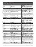
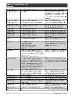
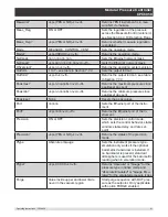
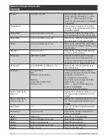
Use Screens in Section 6.4.11 Digital I/O Application to assign conditions or actions to the digital inputs
and the digital outputs. The I/O connector is on upper middle right side of the rear panel.
7.1.1 Digital I/O Specifications
Connector type on Instrument – Phoenix Contact #1827596
Mating Connector – Phoenix Contact #1827761
7.1.1.1 Digital Input
Maximum voltage allowable on digital input pin (referenced to ground pin): 30 VDC
Minimum voltage allowable on digital input pin (referenced to ground pin): 0 VDC
Maximum current allowable into digital input pin: 15 mA
Minimum voltage required to trigger input (referenced to ground pin): 2.5 VDC
Minimum current required to trigger input: 0.5 mA
The digital inputs are connected through a series resistor and then through an optocoupler before being
used internally in the instrument. They require a minimum amount of current before they will trigger. The
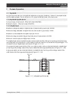
schematic for each digital input can be seen in Figure 7.1.1.1-A
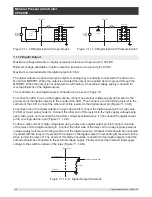
The output of a logic device such as PLC or a control system can be connected directly to a digital input
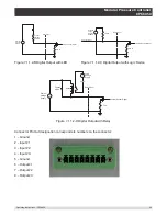
pin as long as the voltage output of the device falls within the range specified above (Figure 7.1.1.1-B).
A pressure switch can be connected directly to a digital input pin as long as the voltage output of the
switch falls within the range specified above (Figure 7.1.1.1-C)
1
2
3
4
5
6
7
8
9
10
11
12
13
14
15
16
Optocoupler
To Internal Input
2 KΩ
Rear Panel
Digital Input
Ground
Figure 7.1.1.1-A Digital Input Schematic

