68
Operating Instructions - CPC6050
Modular Pressure Controller
CPC6050
1
2
3
4
5
6
7
8
9
10
11
12
13
14
15
16
Optocoupler
To Internal Input
2 KΩ
Rear Panel
+
-
Exernal
Supply
Voltage
Output
Logic
Device
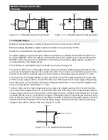
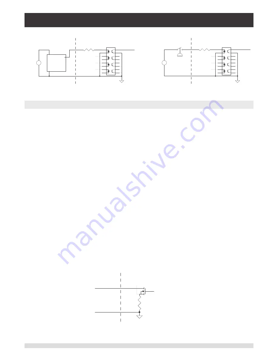
Figure 7.1.1.1-B Digital Input with Logic Device
1
2
3
4
5
6
7
8
9
10
11
12
13
14
15
16
Optocoupler
To Internal Input
2 KΩ
Rear Panel
+
-
Exernal
Supply
Voltage
Pressure
Switch
Figure 7.1.1.1-C Digital Input with Pressure Switch
7.1.1.2 Digital Output
Maximum voltage allowable on digital output pin (referenced to ground pin): 30 VDC
Minimum voltage allowable on digital output pin (referenced to ground pin): 0 VDC
Maximum current allowable into digital output pin: 0.5 A
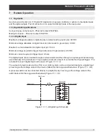
The digital outputs are open drain type outputs, meaning they are directly connected to the drain of an
N-channel MOSFET. When the output is activated the output pin is pulled down to ground through the
MOSFET. When the output is not activated it is left floating. An external voltage supply is needed for
most applications of the digital outputs.
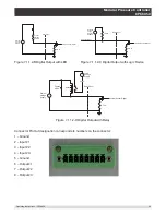
The schematic for each digital output connection can be seen in figure 1A.
To connect an LED to one of the digital outputs, connect an external voltage supply (referenced to the
ground pin of the digital outputs) to the anode of the LED. Then connect a current limiting resistor to the
cathode of the LED. Connect the other end of this resistor to the digital output pin (Figure 7.1.1.2-B)
To connect one of the digital outputs to a logic device first connect the digital output pin to a high value
(10 KΩ or more) pull up resistor. Connect the other end of this resistor to the logic supply voltage being
used, taking care not to exceed the maximum voltage specified above. Then connect the digital output
pin to your logic device input (Figure 7.1.1.2-C).
To drive a high current or high voltage load using a relay and a digital output pin first connect one side
of the relay coil to a digital output pin. Connect the other side of the relay coil to an appropriate external
voltage supply (referenced to the ground pin of the digital outputs). A flyback diode should be connected
in parallel with the relay coil to prevent the voltage on the digital output pin exceeding its maximum rating
when turning the relay off. The anode of this diode should be connected to the digital output pin and the
cathode should be connected to the external voltage supply. Finally connect the load and load supply
voltage to the switch terminals of the relay (Figure 7.1.1.2-D).
0.75 Ω
Internal Control Signal
Digital Output
Rear Panel
Ground
Figure 7.1.1.2-A - Digital Output Schematic

