High-End Pressure Controller
CPC8000
104
Operating Instructions - CPC8000
CAUTION: Further access to the interior of the instrument is NOT recommended.
There are no user-serviceable plumbing or parts inside. In addition to the danger-
ous voltages present (line voltage), there are circuits sensitive to electrostatic
discharge damage.
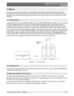
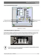
To remove a transducer from the system, swing the front panel open and disconnect the 9-pin D-sub con-
nector from its top. Then use the supplied 3/16 inch Allen wrench to loosen the two cap screws near the
base of the transducer. With both screws disengaged, slide the transducer toward the front opening to
disconnect it from the manifold. If an optional Barometric transducer is present it will occupy a slot to the
far right and will be secured in place with a thumb screw. Loosen the thumb screw and lift the sensor up
and over the retaining pin. Each pressure or barometer module is totally self-contained and including the
pressure sensor and all of its calibration data.
To return the module, or a replacement module to the system slide it frmly back into position to engage
the pneumatic passages with those in the manifold, tighten the two retaining cap screws, and connect
the communication/power D-sub connector. To replace the optional barometer, slide it back into place
over the retaining pin and tighten the thumb screw. Finally, secure the front panel and test that the system
is operational.
In replacing transducer modules the order of position must be maintained according to the pressure limit
of each module; starting with the highest pressure transducer on the left (PRIMARY TRANSDUCER),
and the next lower pressure limit transducer next (SECONDARY TRANSDUCER), and the lowest ranged
transducer to the right (TERTIARY TRANSDUCER). If an optional BAROMETRIC TRANSDUCER is
present it will occupy a diferent type slot to the right of the TERTIARY TRANSDUCER.
If the system will be operated with less than the full complement of three pressure modules (not including
the BAROMETRIC TRANSDUCER) the frst empty slots must be the TERTIARY TRANSDUCER Slot. If
there is just one installed transducer then the SECONDARY TRANSDUCER slot would also be empty. To
be functional, each empty slot must have a pneumatic seal on the manifold. In this case a manifold seal
plate is supplied and attached at the Mensor factory for this purpose. The D-sub connectors for unused
slots can remain unplugged.
10.2.3 Side Panel Removal
On desk-top units the two identical side panels include formed recesses which are used as lift points to
move or carry the instrument over short distances. These side panels are secured to the chassis by three
3mm Allen cap screws accessible inside the lift-recesses. With the cap-screws removed pull the side
panel straight out away from the chassis with enough force to overcome the friction pins which hold it in
position.
Summary of Contents for CPC8000
Page 6: ...High End Pressure Controller CPC8000 6 Operating Instructions CPC8000 NOTES ...
Page 10: ...High End Pressure Controller CPC8000 10 Operating Instructions CPC8000 NOTES ...
Page 24: ...High End Pressure Controller CPC8000 24 Operating Instructions CPC8000 NOTES ...
Page 84: ...High End Pressure Controller CPC8000 84 Operating Instructions CPC8000 Notes ...
Page 112: ...High End Pressure Controller CPC8000 Operating Instructions CPC8000 113 NOTES ...

