background image

High-End Pressure Controller 

CPC8000

 Operating Instructions - CPC8000 

81

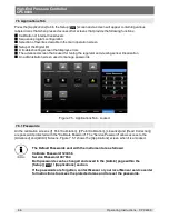
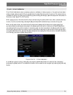
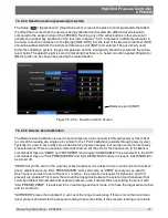
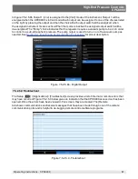
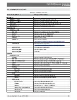
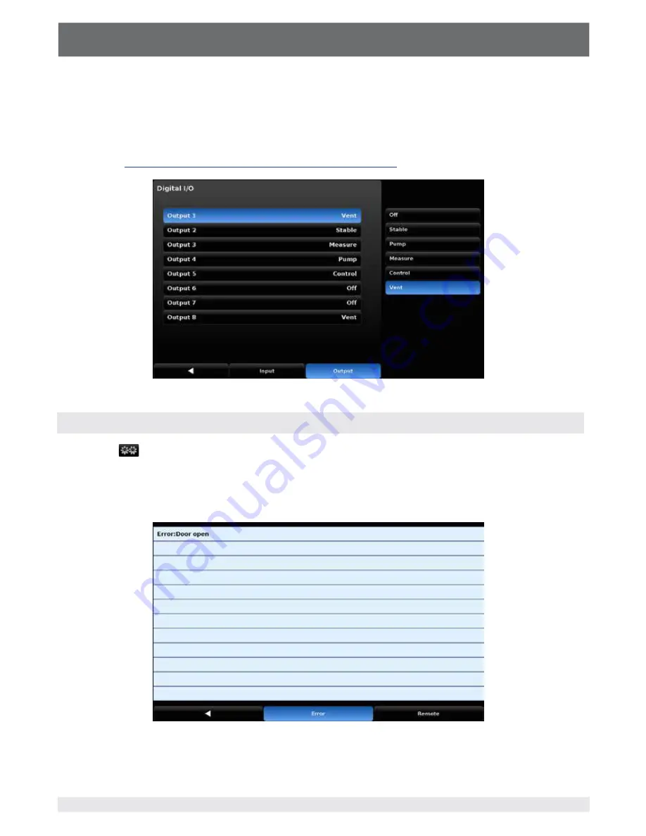
In fgure 7.5.2.5.8b Output 1 (one) is assigned to the [Vent] mode of the instrument. Output 1 will be 

energized when the CPC8000 is in Vent mode. Each output can be assigned to one of the choices listed 

on the right by pressing the output and then the choice. Each output switch will be energized when 

the assigned instrument mode is active. When the mode is inactive the assigned output switch will be 

de-energized. The “Pump” choice indicates that the regulator requires a vacuum pump to be on in order 

to control to a sub-atmospheric pressure. The pump output is used to turn on or of a vacuum pump as 

needed. See 

Section 5.7, Electrical & Communication Connections

 for pinout description.

 Figure 7.5.2.5.8b - Digital Output

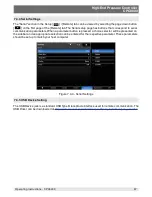
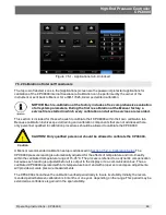
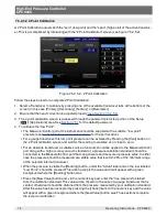
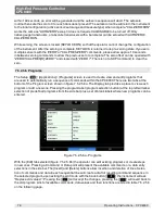
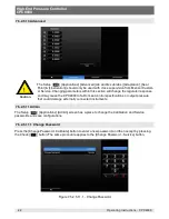
7.5.2.5.9 Troubleshoot 

The Setup [ 

 ] / {Applications] / [Troubleshoot] screen provides a list of internal or remote errors that 

may have occurred. Figure 7.5.2.5.9 below gives an indication that the CPC8000 access door has been 

opened. Once the errors have been viewed in this screen, they are cleared. The [Remote 

tab shows communication send/receive messages that have been made through one of the remote 

communication ports and is helpful in de-bugging remote control software programs.

Figure 7.5.2.5.9 - Troubleshoot

Summary of Contents for CPC8000

Page 1: ...CPC8000 Operating Instructions CPC8000 High End Pressure Controller PN 0018508001V High End Pressure Controller ...

Page 2: ...t and or considerable material damage mortal danger danger of injury will occur if the respective safety precautions are not taken This Caution symbol indicates danger for the system and material if the respective safety precautions are not taken This Notice symbol does not indicate safety notices but information for a better understanding of the facts ...

Page 3: ...ower Switch 14 3 2 2 USB Port 14 3 2 3 Information Label 14 3 2 4 Screen 14 3 2 4 1 Main Screen Features 14 3 2 4 2 Screen Navigation 15 3 3 Main Features 16 4 Specifications 17 4 1 Measure Specifications 17 4 2 Control Specifications 17 4 3 General Specifications 18 4 4 Transducer Removal Replacement 19 4 5 Regulator Ranges 20 4 6 Transducer Choices 21 4 6 1 Transducer Type Range Mode Uncertainty...

Page 4: ...6 2 6 4 Program Data Entry 40 6 2 7 Favorites 41 6 2 8 Status Bar 41 6 2 9 Secondary and Tertiary Displays 42 6 2 10 Limits 43 6 2 11 Bar Graph 43 6 2 12 Pressure Units 44 6 2 13 Pressure Type 44 6 2 14 Operating Modes 45 6 2 14 1 Measure Mode 46 6 2 14 2 Control Mode 48 6 2 14 3 Vent Mode 50 6 2 14 4 State of the isolation valves when the CPC8000 is off 52 7 Setup 53 7 1 General Tab 54 7 1 1 Lang...

Page 5: ...o Calibration 77 7 5 2 5 6 Programs 78 7 5 2 5 7 Favorites 80 7 5 2 5 8 Digital I O 80 7 5 2 5 9 Troubleshoot 81 7 5 2 5 10 Advanced 82 7 5 2 5 11 Admin 82 7 5 2 5 11 1 Change Password 82 8 Remote Operation 85 8 1 Software Functions 85 8 2 Remote Command Set 85 8 3 SCPI WIKA Command Set 93 8 4 SCPI Error Messages and Error Codes 96 8 5 Command Emulation 97 8 5 1 PCS 400 Emulated Commands 97 9 Opti...

Page 6: ...High End Pressure Controller CPC8000 6 Operating Instructions CPC8000 NOTES ...

Page 7: ...ithout specifc factory permission voids this warranty MENSOR MAKES NO WARRANTY OF ANY KIND WITH REGARD TO THIS MANUAL INCLUDING BUT NOT LIMITED TO THE IMPLIED WARRANTIES OF MERCHANTABILITY AND FITNESS FOR A PARTICULAR PURPOSE Mensor shall not be liable for errors contained herein or for incidental or consequential damages in connection with the furnishing performance or use of this material 1 2 Im...

Page 8: ...ll not be held to any liability for any damages sufered or incurred by the end user including but not limited to general special consequential or incidental damages including damages for loss of business profts business interruption loss of business information and the like arising from or in connection with the delivery use or performance of the software program 1 6 Mensor Service Plus Mensor has...

Page 9: ... of Standards and Technology NIST 1 6 3 Accreditations Mensor is registered to ISO 9001 2008 The calibration program at Mensor is accredited by A2LA as complying with both the ISO IEC 17025 2005 and the ANSI NCSL Z540 1 1994 standards 1 7 Packaging for Shipment If the product must be shipped to a diferent location or returned for any reason through a common carrier it must be packaged properly to ...

Page 10: ...High End Pressure Controller CPC8000 10 Operating Instructions CPC8000 NOTES ...

Page 11: ...system should be operated only by trained personnel who are familiar with this manual and the operation of the instrument A condition for trouble free and safe operation of this system is proper transport proper storage installation assembly and proper use as well as careful operation and maintenance Any operation not described in the following instructions should be prohibited The system must be ...

Page 12: ...ound levels above 80 dbA for brief periods when they are exhausted directly to atmosphere A mufer is provided for connection to the vent port It is the operator s responsibility to measure sound levels at whatever point 1 meter from the equipment that has the highest sound pressure level At levels above 80 dbA use of protective ear pieces can reduce these higher levels to a safe level WARNING NOT ...

Page 13: ...vable interchangeable pressure transducers are available in full scale FS ranges from 0 36 to 6 000 psig 7 5 to 6015 psia Each transducer module is confgured with its own calibration parameters on board and have 0 01 IS 50 or optional 0 008 IS 33 uncertainty The three transducers in combination with the internal control valve regulator provide a dynamic output The operator can choose to control pr...

Page 14: ...ith enough force to latch it in to turn the unit ON Push it again to release it to turn the system OFF If power to the instrument is interrupted while ON it will shut down until the power is restored then immediately resume operation 3 2 2 USB Port The front panel USB port is the same as the Host USB port on the rear panel Both are intended for future expansions or software upgrades 3 2 3 Informat...

Page 15: ...on Individual screens are accessed by a series of touches on tabs buttons or icons which open screens within the hierarchy of the instrument Nomenclature that designated a screen and how to navigate to it will be given in this manual in the following structure Icon name Icon Graphic Tab Button Name For example the screen used to set the resolution of the instrument sensor would be designated by th...

Page 16: ...cal Operation Touch the left pointing arrow in the bottom left corner of any setup screen to return to the main screen Full operational descriptions of all of the screens symbols labels and switches are provided in Section 6 Local Operation 3 3 Main Features Up to three highly stable removable interchangeable pressure transducers see Section 10 2 2 Transducer Removal Replacement Each transducer is...

Page 17: ...f a range also known as the full scale value Example for a range of 15 145 Max 145 Min the minimum value of a range Example for a range of 15 145 Min 15 Full Span Max Min Example for 0 145 the Full Span is 145 for 15 145 the Full Span is 160 Reading The value of the sensor output 1 Total Uncertainty k 2 includes hysteresis linearity repeatability reference standard drift and temperature efects ove...

Page 18: ...Response time 33 seconds after a 0 FS step Orientation efects tilt Negligible can be removed with re zeroing calibrate and operate in a horizontal position Shock vibration 2 G s Max Pressure media capability Clean dry non corrosive non combustible non oxidizing gases No oxygen Metals in contact with media 6000 series Aluminum 316 SS Brass Non metals in contact with media Tefon Urethane Silicone RT...

Page 19: ...er transducers or seal plates for the instrument to function Two manifold seal plates are shipped with each unit for this purpose The D sub connectors for unused slots can remain unplugged For more information on transducer re moval replacement see Section 10 2 2 in the Maintenance section Up to three transducers can be present within the CPC8000 The full scale pressure of the highest ranged trans...

Page 20: ...r gauge or 136 bar absolute 1000 psi gauge or 1015 psi absolute 70 bar gauge or 71 bar absolute HP NVR 3000 psi gauge or 3015 psi absolute 210 bar gauge or 211 bar absolute 2000 psi gauge or 2015 psi absolute 135 bar gauge or 136 bar absolute EP NVR 6000 psi gauge or 6015 psi absolute 400 bar gauge or 401 bar absolute 3000 psi gauge or 3015 psi absolute 210 bar gauge or 211 bar absolute 0 1000 200...

Page 21: ...ble control The number of unique readings sec over the remote interface is dependent on the sensor type The sensor update rate of a standard sensor is 30ms or 33 unique readings sec The sensor update rate of a premium sensor is 100ms or 10 unique readings sec This is a technical limitation of the premium sensor required to meet performance specifcations All remote protocols can query faster than t...

Page 22: ...0 365 days Min span Max span 0 18 0 18 psi 0 5 0 5 psi Bidirectional 0 03 FS 180 days 0 5 0 5 psi 5 14 5 psi Bidirectional 0 01 FS 180 days 5 14 5 psi 15 145 psi Bidirectional 0 01 FS 365 days 15 145 psi 15 6015 psi Bidirectional 0 01 IS 50 365 days Premium Transducer Ranges Mode Uncertainty 0 12 to 0 16 5 psia Absolute 0 008 IS 33 365 days 0 18 4 to 0 33 psia Absolute 0 008 IS 33 365 days 0 36 to...

Page 23: ...hat half scale while the uncertainty anywhere in the upper half of the full range is a sliding scale number that is a percent 0 01 of any reading For example a device with a pressure range from 0 to 100 psi with an uncertainty specifcation of Intel liScale 0 01 IS 50 will have an uncertainty of 0 005 psi 0 01 x 50 psi FS on any pressure from 0 psi to 50 psi and an uncertainty of 0 01 of reading 0 ...

Page 24: ...High End Pressure Controller CPC8000 24 Operating Instructions CPC8000 NOTES ...

Page 25: ...h it on and confgure A Quick Start Guide has been placed inside the shipping box containing your instrument This guide provides a quick reference to the pneumatic and electrical connections and an introduction to the opera tor interface It is intended for experienced operators All safety precautions within this manual should be understood and followed 5 2 Unpacking the system Your new instrument w...

Page 26: ... 6 19 16 9 7 0 1 5 16 2 16 1 5 19 5 8 6 19 16 9 7 0 1 5 16 2 16 1 5 front view side view rear view Rack mount High End Pressure Controller CPC8000 Power supply 100 120 VAC 200 240 VAC 50 60 Hz Energy consumption max 140 VA Pressure medium clean dry air or nitrogen Operating temp 15 45 C Serial number 910021 Basic instrument LP NVR 14 5 90 psi 0 105 psi abs Date of manufacture 12 2012 Mensor 201 Ba...

Page 27: ...the minimum to the maximum then back to the minimum pressure of the primary sensor with the desired volume connected to the Measure Control port This will allow the controller to properly compensate for the diference in external volume between what was used at the factory versus what is currently in use This pressure cycle should occur after each power cycle or when the external volume size has be...

Page 28: ... conditions Leave this port open or connect the optional mufer for noise reduction Reference This is the pressure connection to the reference ports of sensors with ranges 50 psi 4 bar gauge The Reference port should be left open to the atmosphere and should NEVER be connect ed to a pressure source The higher the supply pressure connected to the Supply port the higher the pressure which leaves the ...

Page 29: ...8000 a volume close to the volume expected during normal operation can be connected to the Measure Control port WARNING The user must ensure that released pressure medium does not endan ger personnel environment or the instrument Test items with large volumes or long piping runs with small diameter tubing can have a negative efect on the control performance Device under test Vacuum pump if require...

Page 30: ...30 OUTPUT6 NC 31 OUTPUT6 NO 32 OUTPUT7 COM 33 OUTPUT7 NC 34 OUTPUT7 NO 35 OUTPUT8 COM 36 OUTPUT8 NC 37 OUTPUT8 NO 37 Pin Digital Input Output Pin 1 Pin 19 Pin 20 Pin 37 Note USB ports are compliant with the industry standard PIN DESCRIPTION 1 D101 2 D102 3 D103 4 D104 5 EOI 6 DAV 7 NRFD 8 NDAC 9 IFC 10 SRQ 11 ATN 12 SHIELD 13 D105 14 D106 15 D107 16 D108 17 REN 18 GND 19 GND 20 GND 21 GND 22 GND 2...

Page 31: ...pgrade software and download information from the device It has the same function as the USB Host port on the front of the CPC8000 5 7 1 5 USB Device Interface The USB Device jack is a standard USB Type B receptacle interface used for remote communication The USB Driver can be downloaded at http www mensor com download_software_instrument_en_ um WIKA ActiveID 31350 5 7 1 6 RS 232 Interface The RS ...

Page 32: ...d resistive 0 5A 125VAC 1A 24VDC Rated carry current 2A Max switching voltage 125VAC 60VDC Max switching current 1A Max switching power 62 5VA 30W The instrument can be set to respond to the digital inputs and to change the outputs based on certain conditions See section 7 5 2 5 8 ...

Page 33: ...two thirds of the total screen area This area contains the pressure output reading the setpoint the active transducer range units of measure limits and a choice between the control modes Measure Control or Vent The sidebar to the right black feld is used for entering data adjusting environmental settings defning parameters for remote operations and making choices in the confguration Several difere...

Page 34: ...e A word or symbol on a screen which does NOT respond to being touched or pressed is referred to in this manual as a label window monitor or an indicator A label is merely a bit of information appropri ate to the displayed activity while a window is a variable usually a numeric value Also some screens will display a line or more of text messages Labels windows monitors indicators and text are not ...

Page 35: ...ld The upper left corner of the main screen shows either Autorange or Range Hold Although this is a two state button it is not a toggle switch When Autorange is displayed the system will automatically select which of the available transducers up to 3 to use at any time in a process for maximum accuracy When Range Hold is showing the operator has assigned a specifc transducer to be the lone active ...

Page 36: ...on will activate a sidebar data entry method to accept a new setpoint value The setpoint value is displayed in the window just below the Setpoint button on the main screen see Section 6 2 4 The setpoint value can also be adjusted incrementally in the sidebar by use of one of four setpoint entry methods The numeric key pad A numeric step value assigned to the up and down arrow keys A digital step a...

Page 37: ...5 Setup Screen Tabs After regaining the main screen the last visited setup screen will return if Setup is pressed again Operational information for the setup screens and their associated sidebars is contained in Section 7 Setup 6 2 6 Setpoint Entry Methods Pressing the key pad icon in the middle of the top row will display the four line menu as shown below Returns the number key pad to the main sc...

Page 38: ... Max and Minimum Limits There are three action keys below the number keys that operate on the numbers displayed in the input value window Press the Enter key to accept the value showing in the number echo window into the system for immediate use Press the Backspace key to erase the last number entered in the string Multiple presses will back out multiple digits Press the Delete key to delete the e...

Page 39: ...ne digit at a time by activating the corresponding digit with a blue 1 and pressing the Up or Down key For example in the screen below the setpoint is at 50 0000 and the operator would like to change this to 51 0000 52 0000 53 0000 and so on He simply has to touch the digit in the Digital Step that corresponds to the ones digit in the Setpoint thereby activating that digit and then press the Up ke...

Page 40: ...tion Program screen See Section 7 5 2 5 6 Programs for details on how to create edit and save programs Current program and program selection button Figure 6 2 6 4 Program Data Entry Screen After a program has been chosen by pressing the program selection button press the Play button to start the program The Pause button can be pressed at any time to stop the program at the current step then the Pl...

Page 41: ...8 Status Bar Located below the number pad is a status bar consisting of two icons Screen lock Error indicator Figure 6 2 8 Status Bar Screen lock This icon indicated the status of the touchscreen locked or unlocked for manual interaction Error indicator A yellow error indicator triangle indicates that there is an error recorded in the error register Pressing the yellow error indicator will open th...

Page 42: ... the secondary display and the next line is the tertiary display The list of choices are identical for both lines The choices are available for selection in the Setup General Secondary Tertiary Display screen shown in fgure 6 2 9b below An explanation on how to setup and choose options for this area is given in Section 7 1 2 Secondary and Tertiary Display Tertiary Display Secondary Display Figure ...

Page 43: ...e Control Limits are the limits entered into the Setup Control Maxi mum Limits Minimum Limits screen see Section 7 3 1 The Control Limits limit the value that can be entered as a setpoint The Entry limits are equal to the lessor of the Control Limits or the Range Limits when in Range Hold mode Control Limits Entry Limits Range Limits Figure 6 2 10 Limits 6 2 11 Bar Graph The bar graph is always ac...

Page 44: ...ough each set of units and start over at the beginning Pressure units Units menu page 3 of 7 Pressure type Figure 6 2 12 Pressure Units There are several tables of conversion factors for pressure units in Section 11 Appendix The PSI table includes the factors for conversion to or from PSI to all of the other available units Another table uses Bar as the basis for conversion factors to or from most...

Page 45: ...system by means of a solenoid valve Measure Mode Vent Mode Control Mode Figure 6 2 14 Operating Modes Measure Mode In Measure mode the CPC8000 acts like a precision pressure measuring instrument and measures the pressure applied at the Measure Control port If the Control mode was the last used mode before switch ing into Measure mode the last controlled pressure is held in the test assembly See Se...

Page 46: ... pressure is beyond the permissible measurement range the pressure reading is displayed in red instead of white fgures As soon as a pressure of approximately 110 full scale is reached an integrated safety relief valve opens and releases the pressure into the inside of the instrument The regulator is not active in Measure mode The setpoint value can be input while in the Measure mode then Control m...

Page 47: ... Tertiary Transducer Primary Pressure Transducer Optional Barometric Sensor Valve is OPEN Legend Valve is CLOSED Conditional State Popoff Valve set at 10 above transducer range NO NO NC NC NC NO to Vent NO Normally Open NC Normally Closed NOTE The transducer shutof valve yellow valve is closed 1 In Autorange Mode when the system pressure is outside of the connected transducer range 2 In Range Hold...

Page 48: ... the Vent Mode by pressing the Control button In the Control mode the CPC8000 acts as a precision pressure controller and provides a stable pressure output at the Measure Control port In order to ensure that the controller is correctly confgured for the task it is to perform the following measures must be taken and the respective parameters must be set in the Setup menu In order to control pressur...

Page 49: ...Transducer Optional Barometric Sensor Valve is OPEN Legend Valve is CLOSED Conditional State Popoff Valve set at 10 above transducer range Regulator is Active Open to Exhaust if the internal pressure is 2 bar absolute otherwise open to Vent NO NO NC NC NC NO to Vent NO Normally Open NC Normally Closed NOTE The transducer shutof valve yellow valve is closed 1 In Autorange Mode when the system press...

Page 50: ...nt Mode WARNING Venting will cause a sudden loss of pressure in the system and the plumbing connected to the measure control port Care must be taken that the device under test is not damaged during venting WARNING In some cases venting will exhaust high velocity air from the vent port Personnel and sensitive equipment should not be in close proximity to the vent port during venting WARNING In some...

Page 51: ...essure Transducer Optional Barometric Sensor Valve is OPEN Legend Valve is CLOSED Conditional State Popoff Valve set at 10 above transducer range EXHAUST SUPPLY NO NO NC NC NC NO to Vent NO Normally Open NC Normally Closed NOTE The transducer shutof valve yellow valve is closed 1 In Autorange Mode when the system pressure is outside of the connected transducer range 2 In Range Hold mode when anoth...

Page 52: ...000 52 Operating Instructions CPC8000 6 2 14 4 State of the isolation valves when the CPC8000 is of When the CPC8000 is turned of the valves revert to their normal state either Normally Open NO or Normally Closed NC as indicated above ...

Page 53: ...those in red require a second level password to view Information about the CPC8000 Back key Reverts to the previous screen or main screen Language Secondary display Tertiary Display Brightness Volume Load Save Filter Resolution Units Rate Units User Units 1 User Units 1 multiplier User Units 2 User Units 2 multiplier Vent Rate Vent Limit Max limit Min limit Stable limits Stable Delay Rate Setpoint...

Page 54: ...e sidebar will make that language active on every screen in the CPC8000 Figure 7 1 1 Language 7 1 2 Secondary and Tertiary Display The Secondary and Tertiary display areas provide a place to indicate extra data that may be desired during testing or calibration In the General tab there is a selection button labeled Secondary Display and one labeled Tertiary Display Clicking either of these will cha...

Page 55: ...r up and down on the bar graph or simply touching an area on the graph that corre sponds to a brightness level Figure 7 1 3 Brightness 7 1 4 Volume The Volume button within the General tab of the Setup menu provides a place to set the global volume for the instrument s auditory feedback sounds When the Volume button is chosen a gradu ated volume bar graph will appear in the sidebar This shows the ...

Page 56: ...ate stable delay Vent rate Emulation mode gauge abs Filter Resolution Units Rate units Secondary units Brightness Volume Table 7 1 5 Confguration Parameters Explanation on how to set up each confguration can be found below in Section 7 1 6 The Load button within the General tab of the Setup menu shown in fgure 7 1 5 provides a place to choose a saved confguration When the Load button is chosen a c...

Page 57: ...current instrument settings will be saved within this confguration number Instrument settings that are saved in confguration settings are given in table 7 1 5 Figure 7 1 6 Save confguration Confgurations can be used to save time in setting up parameters for specifc calibration needs For example there may be a requirement to calibrate a 100 psi transducer and an upper limit of 105 psi cannot be exc...

Page 58: ... the Setup menu there is a button labeled Filter The right side of the Filter button shows the current flter setting The sensor flter acts on the output pressure indicated on the instrument fltering out small pneumatic and electrical variations in the pressure transducer output This is done by mathematically smoothing the output reading using a low pass flter on the electrical output of the pressu...

Page 59: ...creens of the instrument The user can change the resolution to 4 5 or 6 Figure 7 2 2 Resolution 7 2 3 Units In the Setup Sensor tab there is a button labeled Units When selected the side bar will display a set of 6 selectable units and an Up and a Down arrow used to scroll through a set of 40 diferent units and 2 user defned units Selecting any of these units will change the unit of measure for th...

Page 60: ...defne User Unit 1 and User Unit 2 For User Unit 1 and User Unit 2 the process is the same Selecting the frst User Unit will display a choice of psi bar or pascal in the sidebar Choosing one of these base units will form the basis of the equation that defnes the User Unit chosen Immediately below the frst User Unit button is the User Unit Multiplier button that indicates the current multiplier and ...

Page 61: ...values shown for the limits above the keypad and are relative to the full scale range of the primary sensor Figure 7 2 6 Vent Rate 7 2 7 Vent Limit In the Setup Sensor tab the last button is Vent Limit This is the pressure at which controlled vent stops and the vent solenoid is opened causing the pressure to vent through the vent port uncon trolled The vent limit can be set within the values shown...

Page 62: ... The Maximum Limit and Minimum Limit buttons under the Setup Control screen provide a place to limit the setpoint that can be chosen in the main screen These limits can only be set within the range of the active sensor When the CPC8000 is in Autorange the limits can only be set within the range of the primary transducer which by convention will have the widest range The minimum limit must be lower...

Page 63: ...ssure indica tion will change from white to green For example an operator would like the CPC8000 to show a stable indication only after the pressure output has been at the setpoint 0 002 FS for 2 seconds In this case the Stable Limit should be set at 0 002 and the Stable Delay should be set at 2 The graphic in fgure 7 3 2b illustrates this Figure 7 3 2a Stable Limits and Stable Delay 0 10 20 30 40...

Page 64: ...oint The Rate Setpoint is set in the Setup Control menu The rate setpoint sets the rate of pressure change when the CPC8000 is controlling up or down to a setpoint The rate is limited to 0 001 of the full scale range second to 10 of the full scale range second Figure 7 3 3 Rate Setpoint ...

Page 65: ...n Information about the electrical communication connection hardware is given in Section 5 7 Electrical Connections 7 4 1 Remote Command Set Setup The Command Set button within the Setup Remote tab provides a place for the operator to choose which command set that will be used within remote communication software used to remotely control the function of the CPC8000 When the Command Set button is c...

Page 66: ...emote tab there are buttons that correspond to Ethernet parameters When the button is pressed the numeric key pad or a choice selector will be presented on the sidebar and an appropriate number or selection can be entered for the respective parameter With DHCP turned of a static IP address can be assigned If DHCP is turned on and a lease is obtained successfully the ethernet parameters are grayed ...

Page 67: ...nication parameters When a parameter button is pressed a choice selector will be presented on the sidebar and an appropriate selection can be entered for the respective parameter These parameters should be set up to match your host computer Figure 7 4 4 Serial Settings 7 4 5 USB Device Setting The USB Device jack is a standard USB Type B receptacle interface used for remote communication The USB D...

Page 68: ...arization An administration screen used to manage passwords Figure 7 5 Applications Tab Locked 7 5 1 Passwords All the calibration screens 1 Point Calibration 2 Point Calibration Linearize and Head Correction are password protected with the Calibrate Password The Service Password allows access to the Advanced and Admin Screens Figure 7 5 1 shows the Applications screen when it is unlocked The Defa...

Page 69: ... and calibration components that are not addressed here only personnel qualifed in calibration procedures should be allowed to calibrate the CPC8000 Caution CAUTION Only qualifed personnel should be allowed to calibrate the CPC8000 A Mensor recommended calibration setup is addressed in Section 7 5 2 4 Calibration Setup The CPC8000 pressure reading is automatically adjusted for the efects of temper...

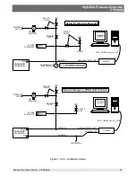
Page 70: ...racy statements as required by ISO IEC 17025 2005 or other applicable standards 7 5 2 3 Calibration Media Gas media are required for calibration The recommended medium is dry nitrogen or clean dry instru ment air 7 5 2 4 Calibration Setup Refer to the calibration setup illustration on the following page see fgure 7 5 2 4 Calibration Setup The illustration shows a typical calibration setup for abso...

Page 71: ...UM GAUGE VAC NOTE DISCONNECT WHEN VACUUM GAUGE RANGE IS EXCEEDED PRESSURE REFERENCE ATMOSPHERE SHUT OFF VALVE VOLUME CONTROLLER VENT LINE REGULATOR SHUT OFF VALVES VENT METERING VALVE PRESS REF PRESSURE STANDARD PRESSURE SUPPLY Setup for Gauge or Differential Pressure Setup for Absolute Pressure CPC8000 Computer optional Computer optional RS232 IEEE488 Ethernet or USB CPC8000 MEASURE CONTROL PORT ...

Page 72: ... to 10 points over the range of each transducer The Remote Zero Calibration is similar to the 1 Point Calibration but is not permanent does not persist through power cycles Procedures for use and interaction with all the calibration screens can be found in the following sections of this manual 1 Point Calibration See Section 7 5 2 5 1 2 Point Calibration See Section 7 5 2 5 2 Linearize Calibration...

Page 73: ...hich will open a numeric key pad With an absolute sensor the instrument should be put in Measure mode with an appropriate high accuracy reference standard connected to the Measure Control port on the back of the CPC8000 If a sub atmospheric zero point is required a vacuum pump can be connected to the Measure Control port to bring the pressure down to a value closer to absolute zero Mensor recommen...

Page 74: ... Pressing the Vent button on the 2 Point calibration screen and wait for the reading to stabilize at or close to zero For an absolute transducer a suitable source of vacuum should be applied to the Measure Control port along with a high accuracy vacuum standard or a pressure calibration standard should be connected to the Measure Control port that can generate and measure a pressure value In eithe...

Page 75: ...utton was These actions completes the High Point calibration The Save button will now be active press it to store the values in the transducer 7 5 2 5 3 Linearize The Linearize application see fgure 7 5 2 5 3a provides a place to record As Found calibration data and to linearize each internal transducer in the CPC8000 using that data An as found calibration can be performed by connecting a suitabl...

Page 76: ... on the Live Cal data Figure 7 5 2 5 3b Live Cal At any time the Factory Cal button can be pressed to revert back to the factory calibration The Reference points and Actual points can also be sent over the remote bus for automated sensor linearizations First ensure the instrument is not in Autorange by sending Sensor n where n is the sensor you wish to linearize or by bringing up the Linearization...

Page 77: ...t through power cycles ofset to correct the reading at a single point similar to the 1 Point Calibration persists through power cycles Typically it is used to set a daily zero as barometric pressure changes but can be used to correct at any measured value There are several commands that can set the zero for the transducers In the Mensor commandset they are ZERO and AUTOZERO and require CALDISABLE ...

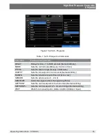
Page 78: ... 5 6 Programs The Setup Applications Programs screen is used to create view and edit programs that are used to automatically run a sequence of commands within the CPC8000 There are two tabs at the bottom of the Program screen shown in fgure 7 5 2 5 6a The Display tab provides a place to view each program or add a new one Pressing the program label program selection button at the top left will allo...

Page 79: ...Vent PTYPE Sets the pressure type Gauge or Absolute RSETPT Sets the rate setpoint in current units Numerical Entry RUNITS Sets the rate denominator time unit min or sec SENSOR Sets the active sensor 1 2 or 3 SEQSTART Starts the sequence from the beginning None SETPOINT Sets the control setpoint for the instrument Numerical Entry SETPOINT Sets the control setpoint in of current range Numerical Entr...

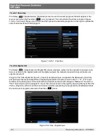
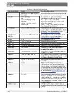
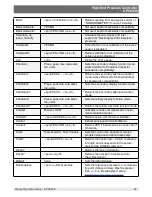
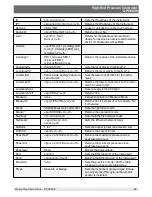
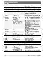
Page 80: ... the operator to assign condi tions or actions to the digital inputs and the digital outputs the default screen will show all inputs and outputs turned of In fgure 7 5 2 5 8a Digital I O Input 1 Input 2 and Input 3 are assigned to the Measure Control and Vent modes respectively When a digital signal switch closure is sent to the 1 2 or 3 input terminal on the back panel of the instrument the instr...

Page 81: ...m pump to be on in order to control to a sub atmospheric pressure The pump output is used to turn on or of a vacuum pump as needed See Section 5 7 Electrical Communication Connections for pinout description Figure 7 5 2 5 8b Digital Output 7 5 2 5 9 Troubleshoot The Setup Applications Troubleshoot screen provides a list of internal or remote errors that may have occurred Figure 7 5 2 5 9 below giv...

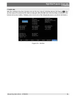
Page 82: ...tor response and may cause the CPC8000 to fail to meet control specifcations or output pressure that could damage externally connected instruments 7 5 2 5 11 Admin The Setup Applications Admin screen has a place to change the Calibration and Service passwords and save confgurations 7 5 2 5 11 1 Change Password Press the Change Password Calibrate button to enter a new password and then accept by pr...

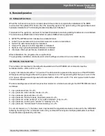
Page 83: ...ument has been powered on and the main screen is displayed press the Setup key and then press the Info tab Information displayed will be the Mensor contact address information the instrument s serial number frmware version and a list of the integrated sensors and other information Figure 7 6 Info Tab ...

Page 84: ...High End Pressure Controller CPC8000 84 Operating Instructions CPC8000 Notes ...

Page 85: ... constants and current settings are stored in a non volatile device 8 2 Remote Command Set This remote command set is the default set available on the CPC8000 All commands must be terminated with a CR and or a LF A query command ends with a for queries The data column represents the response of the CPC8000 All response strings begin either with a space character or an E representing that there is ...

Page 86: ...ag 16 char string General purpose string for customer use Asset_tag sp ssssssssssssssss cr lf Return customer asset tag string Autorange ON or OFF Sets whether the autorange function is enabled or disabled Autorange sp ON or OFF cr lf Returns whether the autorange function is enabled or disabled Autovent ON OFF YES NO 1 0 The autovent function performs a controlled vent of the system when a setpt ...

Page 87: ...2 Press peak rate rate setpt dio units Sets the secondary display function mode Chanfunc2 sp CCCCC cr lf Returns the secondary alternate function mode Chanfunc3 Press peak rate rate setpt dio units Sets the tertiary display function mode Chanfunc3 sp CCCCC cr lf Returns the tertiary alternate function mode Cmdset Mensor SCPI Activates remote command set for instru ment emulation modes Cmdset sp CC...

Page 88: ... of the input bits Bit 8 15 are the status of the output bits Returns an integer between 0 and 65536 DOC mm dd yyyy Sets the date of cal for the active sensor DOC sp mm dd yyyy cr lf Returns the date of cal for the active sensor DOM sp mm dd yyyy cr lf Returns the date of manufacture Error sp text description cr lf Returns the next error in the error queue Errorno sp Enn text cr lf Returns pcs400 ...

Page 89: ...wer control limit for the instru ment in current units Lowovershoot Does not apply to the CPC8000 Lowovershoot sp YES cr lf Returns Yes Measure none Instrument placed in Measure Mode Measure sp YES or No cr lf Returns Yes if instrument is in measure No if otherwise Mode Standby Measure Control Vent Sets the operation mode Mode sp XXXXXX cr lf Returns the operation mode Netmask nnn nnn nnn nnn Sets...

Page 90: ... a multiple computer environment Yes if release is successful No if instrument is being controlled with another computer CCC name of controlling computer or AVAILABLE See Acquire and Unlock Resolution n Sets the number of signifcant digits See decpt Resolution sp n cr lf Returns the number of signifcant digits See decpt Rflter Value in Sets the of the rate flter Rflter sp n nnnnnE nn cr lf Returns...

Page 91: ... sp CCCC cr lf Returns the serial parity Srqmask Stable Error or both Sets the CPC8000 to issue a service request SRQ over the IEEE when the pressure control is stable or an error occurs These are 80 hex and 40 hex respectively Srqmask sp string cr lf Returns stable error or error stable depending on the SRQ Sstop 1 or 2 Sets the serial stop bits Sstop sp X cr lf Returns the serial stop bits Stabl...

Page 92: ...eturns the instrument units in a text string Unlock None Releases Acquire locks See Acquire And Release UpperLimit Value inside primary xducer Range in current units Sets the upper control limit for the active transducer UpperLimit sp n nnnnnE nn cr lf Returns the upper control limit for the active transducer Vent None Instrument placed in Vent Mode Vent sp YES or NO cr lf Returns yes if instrumen...

Page 93: ...n ZERO RUN Start autozero sequence See Section 7 5 2 5 5 Remote Zero Calibration ZERO STOP Stop autozero sequence ZERO INITiate Returns zero status ZERO INITiate Ignored SENSe PRESsure R NAME Returns sensor name string MODE Returns pressure type ABSOLUTE or GAUGE MODE ABS GAUGE Sets the pressure type to absolute or gauge ABS Returns native sensor type 1 for absolute 0 for gauge RESolution Returns ...

Page 94: ...nction not needed VERSion Return SCPI version 1994 0 TEST ELECtronic Returns OK RELay n Returns status of digital output n RELay n ON OFF Turns the digital output on or of n UNIT Note see Table 11 2 Conversion Factors bar NAME n Returns the units string for units code n FACTor n Returns the units conversion for units code n PRESsure bar mbar Pa psi Sets the pressure units PRESsure Returns the pres...

Page 95: ... n Sets the slew rate setpoint in FS sec SLEW Returns the slew rate setpoint TOLerance n Sets the stable window in FS TOLerance Returns the stable window in FS CALCulate LIMit LOWer n Sets minimum control limit LOWer Returns minimum control limit UPPer n Sets maximum control limit UPPer Returns maximum control limit VENT n Pressure at which the vent solenoid opens for an uncon trolled vent VENT Re...

Page 96: ...or which couldn t be categorized in the pre defned errors Table 8 4 Error Codes SCPI Code Error String Returned 0 No error 101 Undefned character 102 Syntax error 103 Undefned separator 104 Parameter data type error 109 Parameter missing 110 Undefned header 113 Undefned command 114 Parameter out of range 313 Calibration data not found 315 Confguration data not found 350 Errorqueue overfow 410 Quer...

Page 97: ...ns current maximum control pressure _pcs4 ctrlmin value Sets minimum control value _pcs4 ctrlmin Returns current minimum control pressure _pcs4 emul Returns ptype emulation mode _pcs4 default Sets default values into instrument _pcs4 err Returns the error number and description _pcs4 exhaustp Returns exhaust pressure _psc4 fltersetting Sets the flter _pcs4 fltersetting Returns the flter _pcs4 flte...

Page 98: ...at the pressure must remain within the stable window for a pressure stable indication _pcs4 stabledelay Returns the number of readings that must be within the stable window before a stable pressure is indicated _pcs4 stablewindow value Sets the pressure window that is used to indicate pressure is stable _pcs4 stablewindow Returns the pressure tolerance allowed for a stable pressure indication as a...

Page 99: ...yurethane foam with a die cut cavity to cradle the instrument with ftting adapters in place and an additional cavity to store related accessories Rugged and weather resis tant the case makes an attractive practical shipping and moving container The case weighs approxi mately 29 pounds 13 15 kg unloaded and can support a load of up to 150 pounds 68 04 kg Nominal dimensions are 15 inches by 24 inche...

Page 100: ...n air driven gas booster mounted in a heavy duty roll bar frame The unit includes an operator control panel with gauges for supply pressure output reference pressure and an output vent valve The system requires shop air to drive the booster and a minimum of 300 psi to 3000 maximum inlet pressure clean dry air or Nitrogen Table 9 4 Specifcations for Input Supply Pressure and Output Pressure Input S...

Page 101: ...ill receive expert care In many cases we can economically upgrade an older instrument to the latest improvements Servicing our own instruments which are used in real world applications keeps us informed as to the most frequent services required We use this knowledge in our continuing efort to design better and more robust instruments 10 2 Troubleshooting ESD PROTECTION REQUIRED The proper use of g...

Page 102: ...the problem of 2 above has no efect Unplug the unit from the power source wall socket then remove the power cord from the instrument The power cord input socket includes two internal fuses Check both fuses for continuity Fuse holder Power cord input socket WARNING When needed use only 2 5 amp 250V SLO BLO 5x20 Fuse 4 Malfunction during operation Switch the system of Wait 5 seconds and switch the s...

Page 103: ...l Replacement The front panel is hinged to allow access to the self contained pressure transducers To open the front panel frst turn of system power then loosen the two captive screws near the right hand edge of the panel The panel can then swing away to reveal the transducers lined up across the interior If the system has not been powered down opening the front panel will trip an inter lock to ve...

Page 104: ...d tighten the thumb screw Finally secure the front panel and test that the system is operational In replacing transducer modules the order of position must be maintained according to the pressure limit of each module starting with the highest pressure transducer on the left PRIMARY TRANSDUCER and the next lower pressure limit transducer next SECONDARY TRANSDUCER and the lowest ranged transducer to...

Page 105: ... Controller CPC8000 Operating Instructions CPC8000 105 11 Appendix Table 11 1 Measurement Units Table 11 2 Conversion Factors bar Table 11 3 Conversion Factors psi Table 11 4 Conversion Factors millitorr WIKA Worldwide ...

Page 106: ...0 degrees Ferenheit ftH2O 60F millimeters of mercury 0 degrees Celcius mmHg 0C millimeters of water 4 degrees Celcius mmH2O 4C millimeters of water 20 degrees Celcius mmH2O 20C centimeters of mercury 0 degrees Celcius cmHg 0C centimeters of water 4 degrees Celcius cmH2O 4C centimeters of water 20 degrees Celcius cmH2O 20C ounce per square inch oz si psf psf tons per quare inch tons sq in tons per ...

Page 107: ...perating Instructions CPC8000 107 meters of sea water mSW grams per centimeter squared g cm2 kilogram per meters squared kg m2 pascals Pa megapascals MPa dynes per centimeter squared dyn cm2 percent full scale FS User 1 User 1 User 2 User 2 ...

Page 108: ...ere kp cm2 9 806650E 01 1 019716E 00 6 pound force foot2 lbf ft2 4 788026E 04 2 088543E 03 7 kilopascal kPa 1 000000E 02 1 000000E 02 8 Centimetres water column 4ºC cmH2O 4ºC 9 806380E 04 1 019744E 03 9 Inch water column 4ºC inH2O 4ºC 2 490820E 03 4 014742E 02 10 Inch water column 20ºC inH2O 20ºC 2 486400E 03 4 021879E 02 11 Inch water column 60ºF inH2O 60ºF 2 488400E 03 4 018647E 02 12 Feet water...

Page 109: ...612629 inH2O 20C 27 72977 0 03606233 inH2O 60F 27 70759 0 03609119 ftH2O 4C 2 306726 0 4335149 ftH2O 20C 2 310814 0 4327480 ftH2O 60F 2 308966 0 4330943 mmHg 0C 51 71508 0 01933672 mmH2O 4C 703 0890 0 001422295 mmH2O 20C 704 336 0 001419777 cmHg 0C 5 171508 0 1933672 cmH2O 4C 70 30890 0 01422295 cmH2O 20C 70 4336 0 01419777 oz si 16 0 0625 psf 144 0 006944444 tons sq in 0 0005 2000 tons sq ft 0 07...

Page 110: ...1715 08 2 inHg 0C 0 00003936995 25400 08909 3 inHg 60F 0 00003948117 25328 53093 4 inH2O 4C 0 0005352534 1868 273977 5 inH2O 20C 0 0005362028 1864 966281 6 inH2O 60F 0 0005357739 1866 458778 7 ftH2O 4C 0 00004460451 22419 25773 8 ftH2O 20C 0 00004468356 22379 59744 9 ftH2O 60F 0 00004464783 22397 50637 10 mTorr 1 0 1 000000022 11 inSW 0C 3 5 salinity 0 0005206091 1920 827359 12 ftSW 0C 3 5 salinit...

Page 111: ...6 735561 166 27 mSW 0C 3 5 salinity 0 00001322347 75623 11663 28 oz si 0 0003093875 3232 1992 29 psf 0 002784488 359 132477 30 tons sq ft 0 000001392244 718265 0575 32 micronHg 0C 1 0 1 000000022 33 tons sq in n a n a 35 hPa 0 001333220 750 0636259 36 MPa 0 0000001333220 7500636 259 37 mmH2O 20C 0 01361955 73 42388114 38 cmH2O 20C 0 001361955 734 2388114 39 mH2O 20C 0 00001361955 73423 88114 ...

Page 112: ...High End Pressure Controller CPC8000 Operating Instructions CPC8000 113 NOTES ...

Page 113: ...www mensor com e mail sales mensor com CPC8000 High End Pressure Controller PN 0018508001V 11 2014 WIKA Alexander Wiegand SE Co KG Alexander Wiegand Straße 30 D 63911 Klingenberg Germany tel 49 93 72 132 9986 web site www wika de fax 49 93 72 132 8767 e mail testequip wika de ...

Reviews: