background image

Operating Instructions - CPG2500 

15


Precision Pressure Indicator

 CPG2500

4  Specifications

Accuracy specifications presented herein are obtained by comparison with primary standards traceable 

to a national metrology institute or recognized international standard organization. These specifications 

are obtained in accordance with the ISO Guide to the Expression of Uncertainty in Measurement (GUM). 

The calibration program at Mensor is accredited by the American Association of Laboratory Accreditation 

(A2LA) as complying with both the ISO/IEC 17025:2005 and the ANSI/NCSL Z540-1-1994 standards. If 

there is an exception to the requirements and recommendations of Z540 during a calibration the excep-

tion is noted on the individual calibration certificate.
Mensor reserves the right to change specifications without notice.

4.1  Transducer Specification

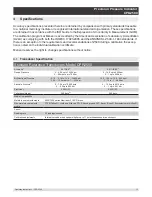
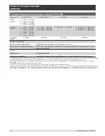
Standard Reference Transducers, Model CPR2550

Accuracy

(1)

0.01%FS

(3)

0.01%IS-50

(2)

Gauge Pressure

0 ... 0.36 up to 10,000 psi 

0 ... 25 mbar up to 700 bar

0 ...14.5 up to 6000 psi 

0 ... 1 up to 400 bar

Bi-Directional Pressure

-0.18. ... 0.18 to -14.5 ... 10,000 psi

-12.5 ... 12.5 mbar to -1 ... 400 bar

-14.5 ... 145 to -14.5 ... 6000 psi 

-1 ... 10 to -1 ... 400 bar

Absolute Pressure

(4)

0 ... 7.5 up to 10,000 psia 

0 ... 0.5 up to 690 bar

0 ... 14.5 up to 6015 psia 

0 ... 1 up to  401 bar

Precision

(5)

0.004%FS

0.004%FS

Calibration Interval

365 days

(6)

365 days

Media Compatibility
Metals in contact with media

6000/7000 series Aluminum, 316 SS, brass

Non-metals in contact with 

media

PTFE (Teflon®), Urethane, Silicone, RTV, Silicone grease, PVC, Epoxy, Buna-N, fluoroelastomers (Viton®)

Sensor
Reading rate

33 readings/second

Calibration adjustments

Internal zero adder and span multiplier, up to 11 point linearization for each sensor

Summary of Contents for CPG2500

Page 1: ...Operating Instructions Precision Pressure Indicator Precision Pressure Indicator CPG2500 PN 0018908001F 02 2017 CPG2500 ...

Page 2: ...t and or considerable damage mortal danger danger of injury will occur if the respective safety precautions are not taken Caution This Caution symbol indicates danger for the system and material if the respective safety precautions are not taken i Notice This Notice symbol does not indicate safety notices but information for a better understanding of the facts ...

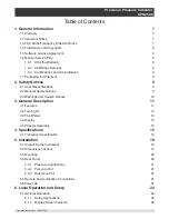
Page 3: ...onsibilities 9 2 2 General Safety Notices 9 2 3 Warnings and Caution Notices 10 3 General Description 11 3 1 Features 11 3 2 Turning On 12 3 3 Front Panel 12 3 4 Display 13 3 5 Chassis Assembly 13 4 Specifications 15 4 1 Transducer Specification 15 5 Installation 18 5 1 Unpacking the Instrument 18 5 2 Dimensions inches 19 5 3 Mounting 20 5 4 Rear Panel 20 5 4 1 Pressure Connections 21 5 4 2 Pressu...

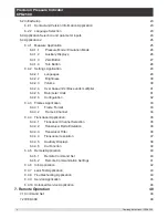
Page 4: ...ts Base units multiplier 31 6 4 2 5 Barometer Units 31 6 4 2 6 Configuration 32 6 4 3 Frames Application 33 6 4 3 1 Frame Format 33 6 4 3 2 Frames Channel 34 6 4 4 Transducer Application 35 6 4 4 1 Transducer Channel Selection 35 6 4 4 2 Transducer Delta Emulation 36 6 4 4 3 Transducer Filter 36 6 4 4 4 Transducer resolution 37 6 4 4 5 Auxiliary Displays 38 6 4 4 6 Cal Function 39 6 4 5 Remote App...

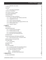
Page 5: ...0 8 Options 62 8 1 Barometer 62 8 2 Barometric Reference 62 8 2 1 Absolute Pressure Emulation 62 8 2 2 Emulation Mode Accuracy 63 8 2 3 Barometric Reference Calibration 63 8 2 4 Barometric reference Specifications 63 8 3 Delta Channel 63 8 4 External Transducers CPT6100 and CPT6180 63 8 4 1 External Pressure Sensor Connection Cable 63 8 5 External Sensor Package D Sub 63 8 6 Analog Output 64 8 6 1...

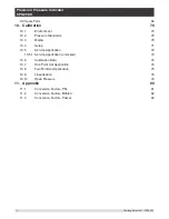
Page 6: ...70 10 3 Media 70 10 4 Setup 71 10 5 Service Application 72 10 5 1 Service Application unlocked 73 10 6 Calibration Data 74 10 7 One Point Cal Application 74 10 8 Two Point Cal Application 75 10 9 Linearization 76 10 10 Head Pressure 78 11 Appendix 80 11 1 Conversion Factors PSI 81 11 2 Conversion Factors Millitorr 82 11 3 Conversion Factors Pascal 83 ...

Page 7: ... liable for errors contained herein or for incidental or con sequential damages in connection with the furnishing performance or use of this material 1 2 Important Notice The product specifications and other information contained in this manual are subject to change without notice Mensor has made a concerted effort to provide complete and current information for the proper use of the equipment If ...

Page 8: ...m or in connection with the delivery use or performance of the software program 1 6 Mensor Service Plus If you have problems and you don t find the answer in this manual contact Mensor at 1 800 984 4200 USA only or 1 512 396 4200 for personal assistance or at any of the contact addresses listed on the rear cover of this manual We are ready to help 1 6 1 After the Warranty Mensor s concern with the...

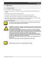
Page 9: ...ith this manual and the operation of the instrument Warning WARNING A condition for trouble free and safe operation of this system is proper transport proper storage installation assembly and proper use as well as careful operation and maintenance Any operation not described in the following instructions should be prohibited The system must be handled with care required for an electronic precision...

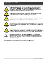
Page 10: ...r the maximum pressure which will be applied otherwise physical injury to the operator or bystanders is possible Caution CAUTION USE THE PROPER PRESSURE MEDIUM Use only clean dry non corro sive gases unless otherwise specified by Mensor This instrument is not designed for oxygen use Caution CAUTION As with most sensitive electronic equipment switch the power switch off before connecting or disconn...

Page 11: ...ensated internal pressure transducers Option to connect two external transducers via a rear mounted RS 232 port in place of the two internal transducers An optional remote transducer in addition to the two internal transducers An optional removable interchangeable internal high accuracy barometric reference transducer providing gauge pressure emulation for absolute ranges and absolute pressure emu...

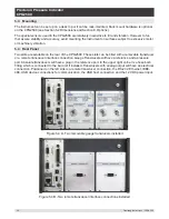
Page 12: ...creen shown below Power Switch ON OFF To see information about the configuration of your new CPG2500 touch the Information Application App icon on the menu and a window will appear listing the Mensor customer service contact model number and the sensors that are installed Press the Measure App to return to the main screen Information Application 3 3 Front Panel The CPG2500 front panel includes a 7...

Page 13: ...ntry screen Text or icons that are displayed but do not respond to being touched are called labels or windows Operators will quickly become accustomed to the particular characteristics of the frequently used buttons Main Screen The main screen or Measure Application appears after power up This screen contains the channel frames and settings button It will remain as configured after a power cycle T...

Page 14: ...14 Operating Instructions CPG2500 Precision Pressure Indicator CPG2500 NOTES ...

Page 15: ...icate Mensor reserves the right to change specifications without notice 4 1 Transducer Specification Standard Reference Transducers Model CPR2550 Accuracy 1 0 01 FS 3 0 01 IS 50 2 Gauge Pressure 0 0 36 up to 10 000 psi 0 25 mbar up to 700 bar 0 14 5 up to 6000 psi 0 1 up to 400 bar Bi Directional Pressure 0 18 0 18 to 14 5 10 000 psi 12 5 12 5 mbar to 1 400 bar 14 5 145 to 14 5 6000 psi 1 10 to 1 ...

Page 16: ...inty with the coverage factor k 2 and includes the intrinsic performance of the instrument the measurement uncertainty of the reference instrument long term stability influence of ambient conditions drift and temperature effects over the compensated range with recommended zero point adjustment every 30 days 2 0 01 IS 50 accuracy Between 0 50 of the full scale the accuracy is 0 01 of half of the fu...

Page 17: ... Low Normal default High Connections Number of integrated transducer selectable Standard 1 reference transducer Optional 2nd reference transducers external transducer internal barometric reference Pressure connections Ranges 6015 psi 7 16 20 female SAE MS adapters provided Ranges 6015 psi Autoclave F250C HIP HF4 Pressure adaptors Standard 1 8 in FNPT Optional 1 4 inch tube 6 mm tube 1 4 in FNPT 1 ...

Page 18: ...inspected for appearance prior to leaving the factory Upon receipt please examine the instrument for shipping damage Report any apparent damage to the carrier immediately In addition to this manual you should have CPG2500 Precision Pressure Indicator Power Supply Fitting adapters ordered Any accessories ordered An envelope containing the calibration certificate ...

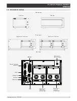
Page 19: ...s Front view Single mount Front view Side view Dual mount Front view 19 rack mount Desk top case Rear Panel IEEE 488 Baro ref port baro ref option Remote Transducer connection RS 232 USB device USB host Ethernet port Power Measure port Channel A 7 16 20 UNF Measure port Channel B 7 16 20 UNF ...

Page 20: ...ble on the rear of the CPG2500 These slots can be filled with a removable transducer or a remote transducer interface connection Gauge Transducers will have a reference and a pressure port Absolute transducers will have a plug in the reference port In the upper right corner is a hose barb fitting which is connected to the baro ref if installed Transducers with analog output will have an electrical...

Page 21: ...4 3 Reference Port The reference port is available on gauge units that have sensors that are not sealed gauge units For these units this port is available to connect to the reference side of the sensor This port is normally left open to atmosphere but may be connected to a stable reference pressure In an absolute pressure trans ducer this port is plugged 5 5 Remote Communication Connections See Se...

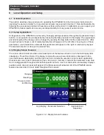
Page 22: ...et of related parameters will appear on the left After choosing one of these parameters a set of selections related to that parameter will appear on the right or a data entry keypad The desired selection or data can be entered here 6 1 2 Display Screen Features The screen shown below provides a brief description of the features shown on a 2 channel display after initialization The left two thirds ...

Page 23: ...6 2 1 Information 6 2 2 Language Selection Pressing the settings application button will open a screen where the language display brightness volume user base units multiplier and configuration loading saving can be changed The current language selections available are shown in the table below Additional language choices will appear on the screen after pushing the Page Down button Language Country ...

Page 24: ...each App is chosen related application parameters will appear on the left two thirds of the screen along with the name of the application and a reduced size icon in the top title section When a parameter is chosen related selec tions sliding scales or a data entry key pad will appear in the input area on the right where the application selection buttons were previously displayed An example of each...

Page 25: ...in figure 6 4 1 A shows the basic Measure App in a three channel instrument The units but ton is always present in each channel When the units button is pressed a selection of imperial and metric units will be displayed on the right figure 6 4 1 B notice that the Units button has a lighter background when the selection menu is active Any unit of measure can be selected for any channel If a baromet...

Page 26: ...can emulate gauge pressure Emulation can be activated simply by pressing the Mode button Figure 6 4 1 1 Mode Label 6 4 1 2 Auxiliary Displays The screen in figure 6 4 1 2 shows all of the possible auxiliary display items that can be included in the Measure App in addition each channel can contain one of two possible calibration functions The aux iliary display item includes Alternate Units Peak an...

Page 27: ...e and the Zero Cal Button is pressed a keyboard will appear to allow a single point calibration If the channel is measur ing gauge pressure pressing the button will set the current reading to zero If the channel is in emulation mode absolute or gauge then the value will not be saved to the sensor but only as a temporary adjust ment while in emulation mode After exiting the emulation mode or after ...

Page 28: ...e tare pressure so that the indicator will display zero Subsequent deviations in pressure will be relative to the tare pressure Notice in the figure below that when active the back ground of the tare button is lighter than the channel background when not active the button back ground is darker than the channel background Figure 6 4 1 4 Tare Button Pressing the tare button again will deactivate the...

Page 29: ... an input screen will appear on the right where selections can be made The Settings App provides a place to change the language display brightness volume user units and barometer units Configuration settings of the unit can also be saved within this application plus the de fault configuration can be activated Figure 6 4 2 Settings application 6 4 2 1Languages The Language parameter provides a sele...

Page 30: ...s Sliding your finger along the bar graph or touching anywhere in the bar graph will change the brightness of the screen After the setting is made and your finger is removed from the screen the menu will revert back to the basic settings menu Figure 6 4 2 2 Brightness 6 4 2 3Volume The Volume setting provides a way to turn on or off the touch screen audio feedback Figure 6 4 2 3 Volume ...

Page 31: ...ay of one atmosphere atm was needed then psi could be chosen as the User 1 base unit and the User 1 multiplier in this case would be 0 068045 When set this way and the user 1 unit has been chosen the user 1 unit will now display the pressure in atm Figure 6 4 2 4 User base units Base units multiplier 6 4 2 5Barometer Units When the Barometer Units Parameter has been chosen a list of Imperial or Me...

Page 32: ...ave button and recalled using the Configuration Load button Simply set all desired parameters then go to Settings Configura tion press one of the numbered Configuration buttons then press the Save button This will save the current configuration in that button To reload a saved configuration at a later time go to Settings Config uration and press the numbered configuration button corresponding to t...

Page 33: ...o bottom The order and number of chan nels displayed can be defined in the Frames Application In addition the optional barometric ref erence transducer can be displayed as a channel as well as an emulated Delta channel Figure 6 4 3 shows the unit in dual frame format with the Frame Format set to display the readings from two transducers A B in a dual frame mode Figure 6 4 3 Frames Application 6 4 ...

Page 34: ...uld be placed in any available position If the Single or Triple frame format is chosen then the channels will appear as shown in each of the respective frame position sets Frame positions sets Single Frame Dual Frame Triple Frame Resulting view in the Measure Application Figure 6 4 3 2 Frames Channel In Figure 6 4 3 2 A the Channels have been set in order for each frame format and the frame format...

Page 35: ...on of the reading In addition the auxiliary display functions and calibration function can be specified here Figure 6 4 4 Transducer Application 6 4 4 1Transducer Channel Selection To set the transducer parameters the transducer channel must be selected Transducer parameters are identical for all channels but can be set differently in each channel Figure 6 4 4 1 shows two displays where channel A ...

Page 36: ... that define the delta display in the Measure App All discrete combinations for adding or subtracting one channel from another are available as a selection These combinations are shown below in Figure 6 4 4 2 Figure 6 4 4 2 Transducer Delta Emulation 6 4 4 3 Transducer Filter The Filter is an electronic filter to smooth out the pressure readings Because of differences in resolution greater filteri...

Page 37: ...sure Indicator CPG2500 6 4 4 4Transducer Resolution The resolution of each transducer channel can be set in the Transducer Application using the resolution parameter The resolution can be set to 4 5 6 or 7 digits Figure 6 4 4 4 Transducer Resolution ...

Page 38: ...ing Auxiliary Dis play 1 2 or 3 and selecting from None Peak Rate or Units Figure 6 4 4 5 A shows auxiliary display 1 2 and 3 set for units peak and rate respectively Auxiliary displays will appear in the Measure App as seen in Figure 6 4 4 5 B Figure 6 4 4 5 A Transducer channel aux displays set to Units Peak and Rate Figure 6 4 4 5 B Auxiliary displays as seen in the Measure App ...

Page 39: ...Choosing Zero will enable the Zero Cal Button in the Measure App Choosing Tare will enable the Tare Button in the Measure App The Tare button and the Zero Button cannot appear on the screen at the same time in the same channel See section 6 4 1 3 and 6 4 1 4 for operation of the Zero and Tare buttons in the Measure App main screen Figure 6 4 4 6 Cal Function ...

Page 40: ...ameters can also be set here Details about the Remote Operation command sets cable requirements etc can be found in Section 7 Remote Operation IEEE 488 Ethernet Serial RS 232 or USB Figure 6 4 5 Remote Application 6 4 5 1Remote Command Set The remote command set parameter provides a choice of the Mensor command set or the WIKA SCPI command set Both sets of commands are listed in Section 7 Remote O...

Page 41: ...ers that require a numeric address for example an IP address will also present a keypad Address entries should conform to the format of the parameter selected The three screens below show examples of each type Figure 6 4 5 2 Remote Communication Settings Numeric entry Numeric address entry Radio button selection i Setting the Ethernet DHCP to yes will have a short delay while the DHCP server is co...

Page 42: ...500 6 4 6 Info Application The Info application displays information about the instrument including Mensor address and email Model number serial number and operating software version Sensor model number serial number range software version Figure 6 4 6 Info Application ...

Page 43: ... amount the leak test is initiated by pressing the Start button If the change in pressure exceeds the Delta parameter before the allotted time in the Time parameter then the Leak Test App will return a red status indication showing the actual difference delta in pressure recorded during time period set in the leak test indicating a failed test Otherwise it will return a green status indication sho...

Page 44: ... that have occurred in the instrument due to a communication or network error Push the Remote button to show commands and responses that have been sent over the remote communication connection If there are any errors in the error queue an error symbol will appear in all screens Figure 6 4 8 A of the instrument Pressing this error button from any screen will open the Troubleshoot application where ...

Page 45: ...ssword for entering this area can be changed Figure 6 4 9 A Service Application locked Press the Enter button to show the numeric keypad to enter a password This will unlock other applica tions Default password is 123456 Enter 123456 and press the check mark to unlock the Service Application Figure 6 4 9 B Service Application Enter Password i Note The default Password is 123456 After entering this...

Page 46: ...he Password can be changed by pressing the Enter button next to the Change Password label This will open a keypad where a new password can be entered and ac cepted by pressing the Check Mark i Note Please make note of a password change and save the new password in a secure location The Unlocked Service Application is the access point to all calibration screens described in Section 10 of this manua...

Page 47: ...Operating Instructions CPG2500 47 Precision Pressure Indicator CPG2500 NOTES ...

Page 48: ...s Mensor default SCPI WIKA The SCPI WIKA mode emulates the WIKA command set in SCPI format 7 2 IEEE 488 IEEE 488 address button Allows the user to set the GPIB address by inputting a numeric value utilizing the touch screen 7 2 1 IEEE 488 2 Commands Command or Query Response Function IDN Returns identification string RST Reset to known state default psi TST Returns 1 OPC Operation completed WAI Re...

Page 49: ...ed in Section 6 4 5 Caution CAUTION Please contact your network administrator for proper settings Caution CAUTION Please consult your computer resources department prior to connect ing this instrument to your network to verify there are no conflicts with existing IP addresses The Ethernet communication port allows the CPG2500 to communicate with computers using 10 100Based T specifications Before ...

Page 50: ... characters sent over the serial port The Serial function allows the user to set the RS 232 serial port settings by selecting from the choices provided Baud 9600 19200 38400 57600 115200 Data Bits 7 8 Stop Bits 1 2 Parity Even Odd None Echo settings On Off 7 4 1 Serial Cable Requirements RS 232 communications are transmitted over a three conductor shielded cable terminated in a standard DB9 connec...

Page 51: ...e of multiple data fields commas are required to separate the fields Queries do not have a data field String text or value numeric data are acceptable in any of the following formats Examples of string data ON OFF mBar inHg Examples of value data 1 1 0 5 678 25 68324e 5 7 7 Command Set Definitions In this manual a data entry made up of alpha characters is defined as a string as opposed to data con...

Page 52: ...le 7 9 CPG2500 Commands and Queries Command Data Response Function See Table Below Returns data per the current output format A sp n nnnnne nn cr lf Returns the A channel pressure read ing AR sp n nnnnne nn cr lf Returns the A channel rate Acquire 15 char string Ex Acquire Test_stand_1 Returns sp YES or NO CCC CCC cr lf This command is used when multiple computers would like to control the instrum...

Page 53: ... Activates remote command set for instrument emulation modes Cmdset sp CCCCC cr lf Returns active command set identifier D sp n nnnnne nn cr lf Returns the D channel pressure read ing DR sp n nnnnne nn cr lf Returns the D channel rate Decpt sp n cr lf Returns the number of decimal points see Resolution Default None Sets the default values Deltafunc A B A C B C A B A C B A B C C A C B Sets the delt...

Page 54: ...p YES or NO cr lf Returns Yes or No List sp PRI 1 cr lf Legacy query Listcal sp PRI sn 1 mmddyy cr lf Returns the calibration date of the ac tive sensor Listrange sp PRI 1 min max cr lf Returns the range of the active sensor Localgravity Value in ft s 2 Sets the local gravity in feet sec 2 Localgravity sp n nnnnnE nn cr lf Returns the local gravity in feet sec 2 Netmask nnn nnn nnn nnn Sets the Et...

Page 55: ...or AVAILABLE See Acquire and Unlock Resolution n Sets the number of significant digits see decpt Resolution sp n cr lf Returns the number of significant dig its see decpt Rfilter Value in Sets the of the rate filter Rfilter sp n nnnnnE nn cr lf Returns the rate filter Runits Sec min hr Sets the rate time unit Runits sp XXXX cr lf Returns the rate time unit Save_cal Save calibration values Save_lin...

Page 56: ...ring Unlock None Releases Acquire locks see Acquire or see Release Window Value in current units Sets the exponential filter window for the active sensor Window sp n nnnnnE nn cr lf Returns the exponential filter window for the active sensor Zero desired pressure or Sets zero to set pressure or for clears previous value CALDISABLE must be OFF NO Zero sp n nnnnnE nn cr lf Returns zero offset for ac...

Page 57: ... Metric 15 millibars MBAR Metric 16 millimeters of water 4 C MMH2O Metric 17 centimeters of water 4 C CMH2O Metric 18 meters of water 4 C MH2O Metric 19 millimeters of mercury 0 C MMHG Metric 20 centimeters of mercury 0 C CMHG Metric 21 torr TORR Metric 22 kilopascals KPA Metric 23 pascals PA Metric 24 dynes per square centimeter DY CM2 Metric 25 grams per square centimeter G CM2 Metric 26 kilogra...

Page 58: ... PRESsure C Returns the pressure from Channel C TEMPerature C Returns the temperature from Channel C RATE C Returns the rate sec from Channel C BAROmetric Returns the barometric pressure CALibration PRESsure C MODE Returns 1 calibrated or 0 not calibrated DATE Returns date of cal MM DD YY DATE i i i Sets date of cal YYYY MM DD ZERO Returns zero offset ZERO n Sets the zero offset ZERO INITiate Igno...

Page 59: ...oes not cause an error does not return a response ERRor NEXT Returns error code description KLOCk ON OFF 1 0 Sets the keylock state PRESet Load known state values SAVe No function not needed VERSion Returns SCPI version 1994 0 TEST ELECtronic Returns OK UNIT PRESsure bar mbar Pa psi Sets the pressure units PRESsure Returns the pressure units NAME n Returns the units string for units code n FACTor ...

Page 60: ...outputs 7 9 6 Interface Functions The CPG2500 responds to the following IEEE 488 2 interface functions SRQ Service Request A service request is asserted whenever an error is encountered When the bus controller issues a serial poll the error will be cleared If the host IEEE board includes automatic serial polling capability turn this feature off in order to view all errors LLO Local Lockout The fro...

Page 61: ...Operating Instructions CPG2500 61 Precision Pressure Indicator CPG2500 NOTES ...

Page 62: ...nce is installed the Pres sure Mode button in the measure application main screen will become active and when pressed will toggle between Absolute and Gauge mode See section 6 4 1 Measure Application 8 1 1 Gauge Pressure Emulation In the Measure Application main screen an absolute transducer channel will indicate Absolute in the mode button this is the default mode When this button is pressed the ...

Page 63: ...cers that are installed The Delta Channel is active when there is more than one transducer attached When active the Delta Channel can be chosen in the Frames App to be displayed in the Measure App and can be configured in the Transducer App as shown in figure 8 3 The Delta channel is enabled automatically when more than one transducer is connected Figure 8 3 Delta Channel Setup 8 4 External Transd...

Page 64: ...um 0 5 VDC 1 part per 400 000 minimum 0 10 VDC 1 part per 800 000 minimum Update Rate 150mS Uncertainties 0 1 VDC 0 010 FS 0 5 VDC 0 010 FS 0 10 VDC 0 010 FS Minimum input impedance of the device measuring the analog output is 1 Megaohm 8 7 Rack Mount Kit The CPG2500 can be supplied with a single or dual 19 rack mount kit Dual Rack Mount Single Rack Mount 8 8 Fittings A variety of fittings are ava...

Page 65: ...nal transducer can be performed remotely using the cable a PC and software provided Figure 8 9 1 Remote Calibration Kit for Internal Transducer 8 9 2 Barometric Reference Calibration Sled The CPG2500 Calibration Sled Kit is available to provide a way to calibrate the barometric reference re motely Calibration of the Barometric Reference can be performed remotely using the Cal sled a PC and the sof...

Page 66: ...ews holding the transducer in the chassis slide the transducer out of the back of the chassis and unplug the ribbon cable from the back of the transducer Figure 8 9 3 1 Transducer Removal 8 9 3 2Barometric Reference Removal To remove the optional Barometric reference first remove three screws holding the top panel of the chassis then remove the top panel This will reveal the barometer Figure 8 9 3...

Page 67: ...Operating Instructions CPG2500 67 Precision Pressure Indicator CPG2500 NOTES ...

Page 68: ... extensive knowledge of the instrument assures you that it will receive expert care In many cases we can economically upgrade an older instrument to the latest improvements Servicing our own instruments which are used in real world applications keeps us informed as to the most frequent services required We use this knowledge in our continuing effort to design better and more robust instruments 9 2...

Page 69: ...Operating Instructions CPG2500 69 Precision Pressure Indicator CPG2500 NOTES ...

Page 70: ...t For maximum accuracy allow the CPG2500 to warm up a minimum of 15 minutes in ambient temperature within the compensated range prior to a calibration In addition the instrument should be at rest on a stable platform that is free of excessive vibration and shock 10 2 Pressure Standards Mensor recommends the use of appropriately accurate primary pressure standards when calibrating this instrument S...

Page 71: ...n The Pressure Standard is normally a deadweight test instrument and the Volume Controller refers to a hand operated variable volume pressure vernier device A diaphragm type vacuum gauge is recom mended over the gauge tube type of vacuum sensor for calibrating sub atmospheric pressures A vacu um pump with the capacity to generate 600 millitorr absolute is recommended Supply Metering Valve Vacuum S...

Page 72: ...word for entering this area can be changed Figure 10 5 A Service Application locked Press the Enter button to show the numeric keypad to enter a password This will unlock other applica tions The Default password is 123456 Enter 123456 and press the check mark to unlock the Service Application Figure 10 5 B Service Application Enter Password i Note The default Password is 123456 After entering this...

Page 73: ...e 10 5 1 Unlocked Service Application From the unlocked Service Application the Password can be changed by pressing the Enter button next to the Change Password label This will open a keypad where a new password can be entered and accepted by pressing the Check Mark i Note Please make note of a password change and save the new password in a secure location The Unlocked Service Application is the a...

Page 74: ...int calibration usually a zero point calibration of each transducer installed can be accomplished in One Point Cal Application The transducer channel is chosen by pressing the Channel button at the top of this screen and then selecting from the list of installed transducer channels For gauge pressure simply expose the reference and the pressure port of the transducer to atmospheric pressure and th...

Page 75: ... Pressure port that can generate and measure a stable pressure value between 600 mTorr absolute and 20 of the active transducer s span 4 When the pressure is stable record the live reading shown on the Two Point Cal screen and enter this value as the Low Reading by pressing the Low Reading button and entering the number followed by the check mark Record the true pressure obtained from the referenc...

Page 76: ... the corresponding reading from the instrument s transducer can be recorded and transcribed into the Linearization Matrix shown in Figure 10 9 A Linearization of each transducer can be performed from this screen by selecting each transducer channel using the channel button in the top left hand corner Figure 10 9 A Linearization Application Data Matrix The Linearization Application automatically po...

Page 77: ...ulated from the data entered in the Linearization Matrix It is a good indication of the overall error of the transducer and will quickly reveal any gross data entry errors that have been made To revert back to the Lineariza tion Matrix press the Matrix Icon Relative Scale Figure 10 9 C Linearization Error Graph When satisfied that all values have been entered correctly press the adjust button and ...

Page 78: ... at an external source that is at a different elevation from the CPG2500 transducer sensing that pressure The four parameters are used to calculate the pressure that is a result of the different elevations It should not be used when calibrating CPG2500 transducers The Head height should be set at zero before cali brating the transducers of the CPG2500 i Notice The Head Pressure should not be activ...

Page 79: ...Pressure Indicator CPG2500 Figure 10 10 B shows the Head Pressure hydraulic screen The height media density media tempera ture and local gravity can be entered here based on the specific setup of the system Figure 10 10 B Head Pressure Hydraulic ...

Page 80: ...rs mBar 16 millimeters of water 4 C mmH2O 4 C 17 centimeters of water 4 C cmH2O 4 C 18 meters of water 4 C MH2O 4 C 19 millimeters of mercury 0 C mmHg 0 C 20 centimeters of mercury 0 C cmHg 0 C 21 torr Torr 22 kilopascals kPa 23 pascals PA 24 dyne per square centimeter Dy cm2 25 grams per square centimeter gm cm2 26 kilograms per square centimeter kg cm2 27 meters of seawater 0 C 3 5 salinity MSW ...

Page 81: ...4330943 10 mTorr 51715 08 0 00001933672 11 inSW 0 C 3 5 salinity 26 92334 0 03714250 12 ftSW 0 C 3 5 salinity 2 243611 0 445710 13 ATM 0 06804596 14 69595 14 Bar 0 06894757 14 50377 15 mBar 68 94757 0 01450377 16 mmH2O 4 C 703 0890 0 001422295 17 cmH2O 4 C 70 30890 0 01422295 18 MH2O 4 C 0 7030890 1 422295 19 mmHg 0 C 51 71508 0 01933672 20 cmHg 0 C 5 171508 0 1933672 21 Torr 51 71508 0 01933672 2...

Page 82: ...0 1 000000000 11 inSW 0 C 3 5 salinity 0 0005206091 1920 827359 12 ftSW 0 C 3 5 salinity 0 00004338408 23049 92831 13 ATM 0 000001315786 760002 2299 14 Bar 0 000001333220 750063 6259 15 mBar 0 001333220 750 0636259 16 mmH2O 4 C 0 0135954 73 5540997 17 cmH2O 4 C 0 001359544 735 5409971 18 MH2O 4 C 0 00001359544 73554 09971 19 mmHg 0 C 0 001 1000 000000 20 cmHg 0 C 0 0001 10000 00000 21 Torr 0 001 1...

Page 83: ...636E 00 1 333220E 01 11 inSW 0 C 3 5 sal 3 904899E 03 2 560885E 02 12 ftSW 0 C 3 5 sal 3 254082E 04 3 073062E 03 13 ATM 9 869230E 06 1 013250E 05 14 Bar 1 00000E 05 1 00000E 05 15 mBar 1 00000E 02 1 00000E 02 16 mmH2O 4 C 1 019744E 01 9 806378E 00 17 cmH2O 4 C 1 019744E 02 9 806378E 01 18 MH2O 4 C 1 019744E 04 9 806378E 03 19 mmHg 0 C 7 500636E 03 1 333220E 02 20 cmHg 0 C 7 500636E 04 1 333220E 03...

Page 84: ...84 Operating Instructions CPG2500 Precision Pressure Indicator CPG2500 38 cmH2O 20 C 1 021553E 02 9 789017E 01 39 MH2O 20 C 1 021553E 04 9 789017E 03 ...

Page 85: ...Operating Instructions CPG2500 85 Precision Pressure Indicator CPG2500 NOTES ...

Page 86: ...SE Co KG Alexander Wiegand Straße 30 D 63911 Klingenberg Germany Tel 49 93 72 132 9986 Web site www wika de Fax 49 93 72 132 8767 E mail testequip wika de Mensor 201 Barnes Drive San Marcos Texas 78666 Phone 512 396 4200 Web site www mensor com Fax 512 396 1820 E mail sales mensor com ...

Reviews: