background image

66

WIKA operating instructions hydraulic high pressure controller, model CPC8000-H

PN 0018708001B  11/2020  EN

 EN

8.  Maintenance and Recalibration

For contact details, please see chapter 1 “General information” or the back page of the operating instructions.

8.1  Admin Passwords

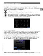
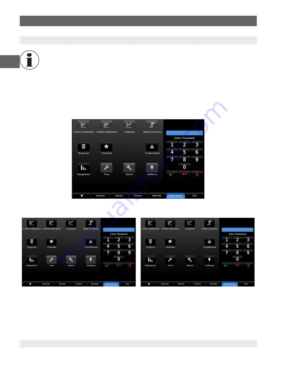
In order to access the Service and Calibration applications that are mentioned in this chapter, use the following passwords.

•  Calibration Applications: 123456

•  Service Applications: 987654

Upon entering the Applications tab, the top and bottom rows will be disabled and greyed (Figure 8.1-A Applications Locked). Using 

the keypad on the right side of the screen and entering the Calibration password will provide access to the top row of applications 

(Figure 8.1-B Calibration Unlocked).  The same process, using the Service password, will allow access to the bottom row of 

applications (Figure 8.1-C Service Unlocked).

Figure 8.1-A Applications Locked

Figure 8.1-C Service Unlocked

Figure 8.1-B Calibration Unlocked

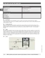
8.2  Maintenance

The CPC8000-H was designed for maintenance-free operation. User maintenance is not recommended, beyond replacement 

of media and transducer removal at calibration intervals. The media should be replaced every 2 years to prevent damage to 

the internal seals.  If you have questions not covered by this manual, call 1-800-984-4200 (USA only), or 1-512-396-4200 for 

assistance, or send an email to tech.support@mensor.com.

8. Maintenance and Recalibration

Summary of Contents for WIKA CPC8000-H

Page 1: ...Operating instructions EN Hydraulic High Pressure Controller Model CPC8000 H Hydraulic High Pressure Controller Model CPC8000 H ...

Page 2: ...perating instructions model CPC8000 H Page 3 86 06 2020 Mensor LP All rights reserved Mensor is a registered trademark of Mensor LP All other brand and product names are trademarks or registered trademarks of their respective companies Prior to starting any work read the operating instructions Keep for later use ...

Page 3: ...11 2 3 Turning On 11 2 4 Front Panel 12 2 4 1 Power Switch 12 2 4 2 USB Port 12 2 5 Display 13 2 6 Scope of Delivery 13 3 Safety 14 3 1 Explanation of Symbols 14 3 2 Intended Use 14 3 3 Improper Use 15 3 4 Responsibility of the Operator 15 3 5 Personnel Qualification 15 3 6 Personal Protective Equipment 16 3 7 Labeling Safety Marks 16 3 7 1 Product Label 16 3 7 2 Symbols 16 3 8 Warnings and Cautio...

Page 4: ... Vent Mode 34 Status Bar and Barometer Reading 34 6 4 2 Settings 35 General Settings 35 1 1 1 1 7 Languages 35 1 1 1 1 8 Auxiliary Displays 36 1 1 1 1 9 Cal Function 36 1 1 1 1 10 Brightness 38 1 1 1 1 11 Volume 38 1 1 1 1 12 Barometer Units 38 1 1 1 1 13 Configurations Load Save 39 Sensor Settings 40 1 1 1 1 14 Sensor Filter 40 1 1 1 1 15 Sensor Resolution 40 1 1 1 1 16 Units Setting 40 1 1 1 1 1...

Page 5: ...Worldwide 69 8 3 2 Environment 70 8 3 3 Pressure Standards 70 8 3 4 Media 70 8 3 5 Setup 70 8 3 6 Calibration Data 71 8 3 7 1 Point Calibration Application 71 8 3 8 2 Point Calibration Application 72 8 3 9 Linearization Application 72 9 Dismounting Return and Disposal 74 9 1 Dismounting 74 9 2 Return 75 9 3 Disposal 75 10 Specifications 76 10 1 Measurement Specification 76 10 2 Approvals and Certi...

Page 6: ...c high pressure controller model CPC8000 H PN 0018708001B 11 2020 EN EN 11 4 Operating fluid 83 12 Appendix 84 12 1 Measurement Units 84 12 2 Conversion Factors PSI 85 Declarations of conformity can be found online at www wika com Contents ...

Page 7: ...nstrument and readily accessible to skilled personnel at any time Pass the operating instructions onto the next operator or owner of the instrument Skilled personnel must have carefully read and understood the operating instructions prior to beginning any work The general terms and conditions contained in the sales documentation shall apply Subject to technical modifications Factory calibrations A...

Page 8: ...as been tested and found to comply with the limits for a Class A digital device pursuant to part 15 of the FCC Rules These limits are designed to provide reasonable protection against harmful interference when the equipment is operated in a commercial environment This equipment generates uses and can radiate radio frequency energy and if not installed and used in accordance with the instruction ma...

Page 9: ...rvices after the warranty for a nominal fee 1 4 2 Calibration Services In addition to servicing our own products Mensor can perform a complete pressure calibration service up to 30 000 psi for all of your pressure instruments This service includes an accredited calibration 1 4 3 Certifications and Accreditations Mensor is registered to ISO 9001 2015 The calibration program at Mensor is accredited ...

Page 10: ...8000 H LP which has a 1 20 pneumatic to hydraulic ratio and the CPC8000 H MP which has a 1 56 ratio Figure 2 1 CPC8000 H with Rolling Rack 2 1 Features Here is a short list of significant features designed into the CPC8000 H Optional 19 rack cabinet with casters Operating range from 0 700 bar 0 10 000 psi for CPC8000 H LP and 0 1 600 bar 23 000 psi for CPC8000 H MP Two removable transducers with u...

Page 11: ...ansducers This module consists of Two intensifiers working in parallel for quick control and larger volumes Priming pump to ensure the DUT and intensifiers are purged Media reservoir tank with sight glass for maintaining an optimal fluid level Filling nozzle for easy refilling of the hydraulic media Sebacate Shell Tellus and distilled water Consult factory for other media Figure 2 2 2 CPC8000 HM 2...

Page 12: ...e Home screen Figure 2 3 Information application 2 4 Front Panel The CPC8000 H front panel includes a 9 color LCD display with touch screen Operator input is accomplished by pressing the words or symbols and the icons presented on the display There is a single discrete on off button and a USB port on the right hand side The front panel also shows the model number designation pressure ranges and br...

Page 13: ...ptional Zero or Tare Current Pressure Units and Mode Optional Bar Graph Operating Modes Auxiliary Displays Buttons Labels and Windows The CPC8000 H touch screen has many buttons with relevant graphic icons or text which when touched will open a related window where changes can be made or information viewed Some of these buttons will toggle from one state to another others present choices or displa...

Page 14: ...cer is configured with its own calibration parameters on board Accuracies are available with 0 01 up to 10 000 psi and 0 014 up to 23 000 psi In addition to the two active range transducers a barometric reference is also available as an option With this option enabled the CPC8000 H can emulate both gauge and absolute pressures The CPC8000 H requires a pneumatic supply pressure of 35 bar which it u...

Page 15: ...ntal protection and know the operating instructions and in particular the safety instructions contained therein the instrument is suitable for the particular application in accordance with its intended use personal protective equipment is available 3 5 Personnel Qualification WARNING Risk of injury should qualification be insufficient Improper handling can result in considerable injury and damage ...

Page 16: ...sonal protective equipment must be provided by the operating company Wear clean and protective safety glasses 3 7 Labeling Safety Marks 3 7 1 Product Label 3 5 6 2 1 4 1 Model 4 Power supply 2 Serial number 5 Power consumption 3 Date of manufacturing 6 Fuse 3 7 2 Symbols Before mounting and commissioning the instrument ensure you read the operating instructions CE Communauté Européenne Instruments...

Page 17: ...paratus attached to the controller must be adequate for the maximum pressure which will be applied otherwise physical injury to the operator or bystanders is possible CAUTION USE THE PROPER PRESSURE MEDIUM Use only clean dry air or nitrogen for the CPC8000 HC and only specified medium on the CPC8000 HM unless otherwise specified by Mensor CAUTION As with most sensitive electronic equipment switch ...

Page 18: ...rage instructions to prevent injuries caused by the weight of the CPC8000 H If the instrument is transported from a cold into a warm environment the formation of condensation may result in instrument malfunction Before putting it back into operation wait for the instrument temperature and the room temperature to equalize 4 2 Packaging and storage The CPC8000 H is packaged inside a custom crate and...

Page 19: ...tatic discharge The correct use of grounded working surfaces and personal armbands is required 5 1 Mounting If ordered without a rolling rack and casters it should be installed on a stable surface Avoid mounting the insturment on surfaces subject to motor or machinery vibration and far away from doors windows heating systems and air conditioning vents The CPC8000 H can optionally be installed in a...

Page 20: ...upply to the intensifier while in control mode 5 2 1 2 CPC8000 HM The CPC8000 HM contains 3 ports the drive air measure control CPC8000 HC and measure control DUT The pneumatic supply pressure uses a male 6mm tube fitting This port requires at least 8 bar 115 psi of pressure but it can also use up to the full supply pressure of the CPC8000 HC This pressure is used to actuate the isolation valves a...

Page 21: ...tween the two modules See section 8 Remote Operation for connections and commands for operation over IEEE 488 Ethernet USB or RS232 ports 5 2 2 1 USB host The USB host port is intended for future expansions or software upgrades This port can also be accessed through the front panel 5 2 2 2 Interface port The interface port is a direct communication between the CPC8000 HC module and the CPC8000 HM ...

Page 22: ... instrument on and connect pressure to the Supply port 4 Enter the lowest setpoint available and press Control This will begin the priming sequence in the CPC8000 H 5 A mixture of air and liquid will leak out of the loosened fitting 6 Once the air is released from the system a steady stream of liquid should appear at the loosened fitting 7 Tighten the fitting and place the instrument in Vent mode ...

Page 23: ...23 WIKA operating instructions hydraulic high pressure controller model CPC8000 H PN 0018708001B 11 2020 EN EN ...

Page 24: ...icult to remove the power cord The instrument is not intended for connection of long distance lines i e lines within a building that are longer than 30 m or that leave the building including lines of outdoor installations 6 1 2 Setup Applications Configuration of the CPC8000 H is achieved by changing settings accessed through the Application App buttons Local operation is accomplished by observing...

Page 25: ...2 1 and 6 2 2 are provided first so that the operator can initially check the information screen to verify the installed components and to change the language if needed 6 2 1 Information Application Select the Settings application on the top right of the screen and navigate to the information application The information tab will contain the Mensor contact installed transducers installed regulator ...

Page 26: ...ngs button will display the settings application with General Sensor Control Remote Applications and Information tabs Selecting the Keypad button will display options for a Number Pad Number Pad Step Percent Step Digital Step and Programs Selecting the Favorites button will display a list of sequences that have been saved in Favorites in the Application tab 6 4 Applications 6 4 1 Main Screen The m...

Page 27: ...tween ranges The primary range will always be listed on top and the secondary range will be beneath Range Hold Figure 6 4 1 1 Range Hold 6 4 1 2 Setpoint By default the Setpoint button is enabled on the screen with a keypad accessible on the right third Figure 6 4 1 2 B The Setpoint button allows the user to enter the desired pressure value within the range of the transducers and module inside the...

Page 28: ...h the blue text box the numbers will turn red and the setpoint change will not be accepted To clear an entry select the cancel button and the blue text box will be reset The backspace button is used to clear the last character that was entered Figure 6 4 1 3 Keypad 6 4 1 4 Number Pad Step The number pad step method provides the same keys as the numeric keypad and also includes up and down buttons ...

Page 29: ... the top right to go back to the home screen From here press the specific percentage or pressure value and the setpoint will immediately change to the chosen setpoint The up and down arrows at the bottom right of the screen allow for nudging the pressure reading by the increments displayed to the right These increments can be changed using the Digital Step application 6 4 1 4 2 Figure 6 4 1 4 1 B ...

Page 30: ...med into the unit and saved and used in the Program portion of the keypad entry screen Programs can be created edited deleted and saved in the Program application located under the Settings then Application tab The example program Figure 6 4 1 4 3 shows the selection of program named Zero and the sequence it will start when the play button is pressed The play button can be pressed again to pause t...

Page 31: ...ayed When the Units button is pressed a selection of imperial and metric units will be displayed on the right Here the user can select which active units will be used when displaying the pressure reading on the main screen The Pressure Type button is a label indicating the native mode of the transducers being used absolute or gauge When an optional barometer is installed the button becomes selecta...

Page 32: ...e of the instrument but can be adjusted to any desired limit within the transducer range This limits will also limit the value that can be entered as a setpoint If a value outside this limit is entered the instrument will display the value in red Control Limits Figure 6 4 1 7 Bar Graph Limits Bar Graph 6 4 1 8 Auxiliary Displays There are two spaces on the screen reserved for auxiliary displays Th...

Page 33: ...ll turn red 6 4 1 9 2 Control Mode The Control mode is activated by pressing the Control button in the bottom center of the screen When selected it will become highlighted blue Figure 6 4 1 9 2 A During control mode the CPC8000 H acts as a precision pressure controller and delivers pressure to the Measure Control DUT port When this mode is initiated from Vent Figure 6 4 1 9 2 B the instrument will...

Page 34: ...hscreen lock unlocked and the error flag as well as the optional barometric reference reading The remote connectivity icon will be highlighted green if a remote connection is active This connection can be made using an IEEE 488 RS 232 Ethernet or USB connection The settings for these interfaces can be found in the Remote Setttings section The touchscreen lock icon will switch to the locked positio...

Page 35: ...gs Application Figure 6 4 2 Settings Application 6 4 2 1 General Settings The general settings screen options allows the user to change the language auxiliary displays main screen calibration functions brightness volume optional barometer units and loading saving configurations All of these settings will change the way the main screen of the instrument is configured By default the general applicat...

Page 36: ...n measured by the instrument These values can be reset by pressing the reset button on the main screen Rate The rate display will show the changing rate of pressure in the current units The time factor will be per second or per minute and this can be chosen on the main screen in the auxiliary display section Sensor 3 This option will display the pilot sensor pneumatic pressure in the current press...

Page 37: ...esired During the zeroing process the touchscreen will be locked and the sequence text will appear on the right side of the screen that lets the user know the process is ongoing Although the screen is locked the red can still be pressed to cancel the process and unlock the screen Zero Button Figure 6 4 2 1 3 A Zero Button Tare Function When the tare option is chosen it will become displayed on the...

Page 38: ...nd pressing a location on the green bar graph on the right side of the screen Figure 6 4 2 1 5 This can be adjusted from 0 to 100 and the volume setting can be saved to a configuration By default the volume is set to 70 6 4 2 1 6 Figure 6 4 2 1 5 Volume Barometer Units The barometer units are selected on the general tab by pressing Barometer and then selecting the units on the right side of the sc...

Page 39: ...ected a list of 8 different configurations will appear on the right side of the screen Figure 6 4 2 1 7 A These configurations can be chosen by pressing the configuration button and selecting the button when prompted to load the selected configuration Figure 6 4 2 1 7 B To save the current settings to a configuration select the Save button and then select a configuration and press the button Figur...

Page 40: ...stable reading for some pressure units By default the filter is set to Normal users can select varying degrees of filtering for the current units by selecting Off Low or High 6 4 2 2 2 Sensor Resolution The resolution of the displayed pressure value can be set in the Sensor settings using the Resolution button The resolution allows the user to select between 4 and 6 digits of resolution on the sen...

Page 41: ...keypad in the side bar where a new multiplier can be entered These two choices are used to calculate the value of the User Units by following the equation User Unit 1 base unit x Multiplier For example if a unit is needed that is not currently available from the 40 choices for instance tons per square meter tsm then the psi conversion factor for this can be found and is 1 psi 0 703069 tsm In this ...

Page 42: ...en on the Main screen This is often used to protect a DUT range that is smaller than the CPC8000 H range 6 4 2 3 2 Figure 6 4 2 3 1 Minimum Limit Stable Limits and Delay The Stable Limits can be found in the Control application by pressing the Stable Limits button Figure 6 4 2 3 2 A The stable limit setting provides a tolerance window around the setpoint that will determine whether the instrument ...

Page 43: ...within the Control application by pressing Vent Limit Figure 6 4 2 3 3 This is the pressure at which the controlled vent stops and the vent solenoid is opened causing the pressure to vent through the vent port uncontrolled The vent limit can be set within the values At this pressure the pneumatic pressure will be relieved through the vent port on the CPC8000 HC and the hydraulic pressure will be r...

Page 44: ...ure is not reached it will cycle the priming pump again This process will continue until the Tank Pump value has been reached The Tank Pump has a default value of 10 cycles but can be set anywhere between 3 and 99 Figure 6 4 2 3 4 Tank Pump 6 4 2 4 Remote Settings The Remote settings can be accessed by entering the Settings application from the Main screen and choosing the Remote tab on the bottom...

Page 45: ... 4 2 4 The active command set will be highlighted blue changing to a different command set will allow the CPC8000 H to automatically switch to the new communication format 6 4 2 4 2 Termination Character The Termination Character button within the Remote application provides an option for the user to select the desired termination character in the output string of the instrument Figure 6 4 2 4 2 I...

Page 46: ...ebar and an appropriate number or selection can be entered for the respective parameter With DHCP turned off a static IP address can be assigned If DHCP is turned on and a lease is obtained successfully the ethernet parameters are greyed and inactive but show the newly assigned lease If a DHCP server fails to respond DHCP will automatically turn off Turning DHCP off allows the ethernet parameters ...

Page 47: ...ng and upgrading the instrument More information about the service applications can be found in Section 9 Maintenance and Recalibration Figure 6 4 2 4 5 Serial Settings 6 4 2 5 1 Programs The Programs application is accessible in the Applications tab This application is used to create view and edit programs that are used to automatically run a sequence of commands within the CPC8000 H There are tw...
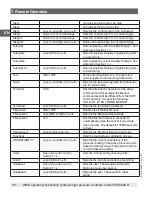
Page 48: ... and pressing the will revert back to the old program A list of the available commands data values and functions are shown below Figure 6 4 2 5 1 B Edit Programs Program Commands DELAY Delay for time 0 0 to 3600 0 seconds Numerical Entry SETPOINT Changes the setpoint to a percentage of Full Scale MODE Sets the mode of the instrument Control Measure or Vent WAIT Waits for a manual input or stable c...

Page 49: ... Troubleshooting The Troubleshooting application is accessible on the Applications tab This application is used to observe any mechanical failures software errors or remote communication errors The two tabs on the bottom of the screen allow the user to view the error log or remote log Figure 6 4 2 5 3 The Errors display is active upon entry of the Troubleshooting application Any error messages wil...

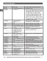
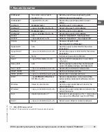
Page 50: ... GPIB address by inputting a numeric value utilizing the touch screen 7 3 1 IEEE 488 2 Commands Command Response Function IDN Returns identification string 7 4 Ethernet The Ethernet function allows the user to set the following by inputting a numeric value in each separate field IP Netmask Gateway Port DHCP settings Set the Ethernet communication parameters as described in 6 4 6 Remote Settings Ap...

Page 51: ...1 stop bit no parity and no echo If echo is ON the CPC8000 H will immediately echo back characters sent over the serial port The Serial function allows the user to set the RS 232 serial port settings by selecting from the choices provided Baud 9600 19200 38400 57600 115200 Data Bits 7 8 Stop Bits 1 2 Parity Even Odd None Echo settings On Off 7 5 1 Serial Cable Requirements RS 232 communications ar...

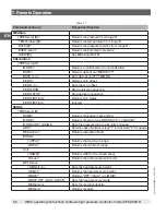
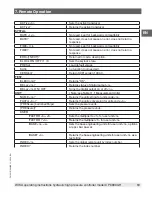
Page 52: ...FF mBar inHg Examples of value data 1 1 0 5 678 25 68324e 5 7 6 2 Command Set Definitions In this manual a data entry made up of alpha characters is defined as a string as opposed to data containing only numbers such as Enter 1 for ON or 0 for OFF where 1 and 0 are defined as values Command Any command or query listed in Table 7 6 4 For commands that take boolean data the following strings are acc...

Page 53: ... cr lf Returns pressure readings of all transducers on the active channel including the barometer Asset_tag 16 char string General purpose string for customer use Asset_tag sp ssssssssssssssss cr lf Return customer asset tag string Autozero none Re zero all the ranges These adjustments are not password protected and are not saved through power cycles This command takes approximately 60 seconds but...

Page 54: ...ntification string for the barometer Barocaldisable YES NO Not used kept for backwards compatibility Barocaldisable sp YES or NO cr lf Not used kept for backwards compatibility Barounits See units code or text in Section 11 4 Sets the barometer engineering units Note this only effects the displayed output on the screen not any remote responses Barounits sp CCCC cr lf Returns the barometer units in...

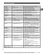
Page 55: ... FilterWin nnn Set the filter window as a floating point value in pressure FilterWin sp n nnnnnE nn cr lf Returns the filter window Gateway nnn nnn nnn nnn Sets the Ethernet gateway address Gateway sp nnn nnn nnn nnn cr lf Gets the Ethernet gateway address Gauge sp YES or NO cr lf Returns if the primary transducer is native gauge Height value in inches Sets the head pressure height in inches Use a...

Page 56: ...e transducers and turn downs Listcal sp PRI sn 1 mmd dyy SEC sn 1 mmd dyy TER sn 1 mmd dyy BAR sn mmd dyy cr lf Returns list of available transducers and turndowns calibration dates Listrange PRI 1 min max SEC 1 min max TER 1 min max Bar min max Returns the ranges of the installed transduc ers Localgravity Value in ft s 2 Sets the local gravity in feet sec 2 Localgravity sp n nnnnnE nn cr lf Retur...

Page 57: ...led Ptype sp CCCCC cr lf Returns GAUGE GAUGE EMULATION ABSOLUTE or ABSOLUTE EMULATION Returns the current pressure type and notes if it is an emulated pressure type Range sp n nnnnnE nn cr lf Alias for RangeMax See RangeMax RangeMax sp n nnnnnE nn cr lf Returns the maximum range of the active transducer in the current units RangeMin sp n nnnnnE nn cr lf Returns the minimum range of the active tran...

Page 58: ...tableWin sp n nnnnnE nn cr lf Alias for RStableWindow See RStableWindow RStableWindow nnn Set the rate stable window as a FS second RStableWindow sp n nnnnnE nn cr lf Returns the rate stable window Runits Sec min hr Sets the rate time unit Runits sp XXXX cr lf Returns the rate time unit Sbaud 9600 19200 38400 57600 115200 Sets the serial baud rate Sbaud sp XXXX cr lf Returns the serial baud data S...

Page 59: ...ial parity Sparity sp CCCC cr lf Returns the serial parity Srqmask Stable Error or both Sets the CPC8000 H to issue a service request SRQ over the IEEE when the pressure control is stable or an error occurs These are 80 hex and 40 hex respectively Srqmask sp string cr lf Returns stable error or error stable depending on the SRQ Sstop 1 or 2 Sets the serial stop bits Sstop sp X cr lf Returns the se...

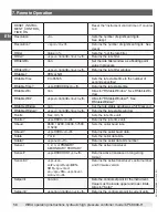
Page 60: ...c ers in current units Termchar CCC Set the termination character for the active command set for example the Mensor command set will be different from the SCPI command set Accepts the following CRLF CR LF EOI NONE DEFAULT Termchar sp CCCC cr lf Returns the termination character Timeouten ON or OFF Enables the Ethernet timeout Timeouten sp YES or NO cr lf Returns the Ethernet timeout state Timeouts...

Page 61: ...upper control limit for the active transducer Vent None Instrument placed in Vent Mode Vent sp YES or NO cr lf Returns YES if instrument is in Vent NO if otherwise Vent_Limit nnn Set the pressure where the vent valve will open completely during a controlled vent Vent_Limit sp n nnnnnE nn cr lf Returns the vent limit in current units VENT_RATE nnn Set the controlled vent rate VENT_RATE sp n nnnnnE ...

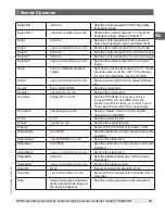
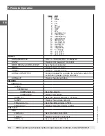
Page 62: ... ZERO RUN Start autozero sequence ZERO STOP Stop autozero sequence ZERO INITiate Returns zero status ZERO INITiate Ignored SENSe PRESsure R NAME Returns transducer name string MODE Returns pressure type ABSOLUTE or GAUGE MODE ABS GAUGE Sets the pressure type to absolute or gauge ABS Returns native transducer type 1 for absolute 0 for gauge RESolution Returns resolution float RANGe UPPer Returns th...

Page 63: ...ded VERSion Return SCPI version 1994 0 TEST ELECtronic Returns OK RELay n Returns status of digital output n RELay n ON OFF Turns the digital output on or off n UNIT Note see Table 11 1 Measurement Units NAME n Returns the units string for units code n FACTor n Returns the units conversion for units code n PRESsure bar mbar Pa psi Sets the pressure units PRESsure Returns the pressure units USER FA...

Page 64: ...rol VENT Sets the mode indicated MODE Returns the mode string STABle Returns 1 if stable 0 if not AUTOvent ON OFF 1 0 Autovent causes the controller to vent when a setpt of 0 is sent while in gauge or gauge emulation AUTOvent Returns the autovent state SOURCE PRESsure LEVel IMMediate AMPLitude n Sets the setpoint AMPLitude Returns the setpoint SLEW n Sets the slew rate setpoint in FS sec SLEW Retu...

Page 65: ... vent goes to atmosphere SYSTem DETECT SLOW FAST CANCEL Starts or stops controller adaption routine Note There is no difference between slow and fast Both start the same controller adaptation process and are only for backwards compatibility DETECT Returns status of controller adaption routine where the response is 0 OK 1 active 2 leakage or no pressure supply 3 pressure supply too high or wrong mo...

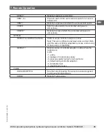
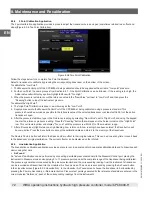
Page 66: ... the screen and entering the Calibration password will provide access to the top row of applications Figure 8 1 B Calibration Unlocked The same process using the Service password will allow access to the bottom row of applications Figure 8 1 C Service Unlocked Figure 8 1 A Applications Locked Figure 8 1 C Service Unlocked Figure 8 1 B Calibration Unlocked 8 2 Maintenance The CPC8000 H was designed...

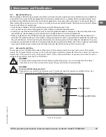
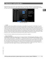
Page 67: ...he product pending external vendor parts or equivalent parts availability The production life cycle is defined as the time from the product series launch to the announcement of discontinuation typically 8 to 10 years All repairs associated with the chassis or internal modules should be performed by Mensor due to the complexity of performing these repairs Replacement of measurement transducers and ...

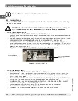
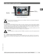
Page 68: ... within the CPC8000 HC Remove the optional barometric reference transducer with the thumb screw If the screw is too tight to remove by hand a small slotted screwdriver may be used 5 To replace or reinstall these transducers install each in the reverse order as the removal process Figure 8 2 3 A CPC8000 HC Front View CPC8000 HM Hydraulic Module 1 Vent the system by placing the controller in Vent mo...

Page 69: ...8000 H operated within its temperature band and with proper zero and span adjustments will provide accurate pressure measurements The CPC8000 H should have the calibration verified periodically to ensure stability The recommended calibration interval for this instrument is given in the Specifications section under Calibration Interval in Section 10 1 WARNING Performing calibration on components wi...

Page 70: ...nds the use of appropriately accurate primary pressure standards when calibrating this instrument Such standards should be sufficient so that when the techniques of the ISO Guide of the Expression of Uncertainty in Measurement GUM are applied the instrument meets its accuracy statements as required by ISO IEC 17025 2017 or other applicable standards 8 3 4 Media The recommended calibration medium f...

Page 71: ...ld be factored into the uncertainty analysis Figure 8 3 6 Calibration Data 8 3 7 1 Point Calibration Application A single point calibration usually a zero point calibration of each transducer installed can be accomplished in 1 Point Calibration Application Figure 8 3 7 One Point Calibration The transducer is chosen by pressing the Primary Secondary or Barometer button at the bottom of this screen ...

Page 72: ...nce pressure reading Press the Reading button that will appear in the Actual column on the High Point row This cell remain yellow and display Too Low until the pressure is within 20 of the maximum range 7 After all four values High Reference High Reading Low reference Low reading have been entered the Save button will become active Press the Save button to accept the calibration data and store it ...

Page 73: ...rresponding point under the Actual column will accept that reading into that point Subsequent pressure points generated by the pressure standard are accepted and recorded in the same way After all points are entered press the Save button to linearize the internal transducer based on the Live Cal data At any time the Factory Cal button can be pressed to revert back to the factory calibration Remote...

Page 74: ...juries and damage to property and the environment Before storage of the dismounted instrument following use wash or clean it in order to protect persons and the environment from exposure to residual media Wear the requisite protective equipment see Section 3 6 Personal Protective Equipment Observe the information in the material safety data sheet for the corresponding medium WARNING Risk of burns ...

Page 75: ... original packaging or a suitable transport packaging To avoid damage 1 Wrap the instrument in an anti static plastic film 2 Place the instrument in the same packaging as it arrived See Section 4 Transport Packaging and Storage for details 3 Label the shipment carrying case as carriage of a highly sensitive measuring instrument Information on returns can be found under the heading Service on our l...

Page 76: ... by the total measurement uncertainty which is expressed with the coverage factor k 2 and includes the following factors the intrinsic performance of the measuring instrument the measurement uncertainty of the reference instrument long term stability influence of ambient conditions drift and temperature effects over the compensated range during a periodic zero point adjustment 2 The precision is t...

Page 77: ...chnical drawings Weight approx 16 7 kg 37 lbs Display Screen 9 0 colour TFT with touchscreen Resolution 4 7 digits Input methods capacitive touchscreen Connections Pressure connections 7 16 20 F SAE Pressure adapters 6 mm FITOK threaded pipe connection others on request Filter elements all pressure ports have 40 micron filters Permissible pressure media Dry clean air or nitrogen Overpressure prote...

Page 78: ...tificate Calibration 9 Standard A2LA calibration certificate standard on factory Optional DKD DAkkS calibration certificate 8 Warning This is class A equipment for emissions and is intended for use in industrial environments In other environments e g residential or commercial installations it can interfere with other equipment under certain conditions In such circumstances the operator is expected...

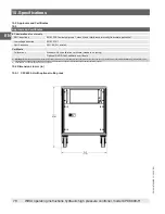
Page 79: ...79 WIKA operating instructions hydraulic high pressure controller model CPC8000 H PN 0018708001B 11 2020 EN EN 10 Specifications ...

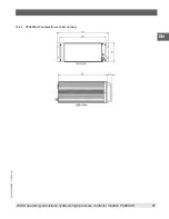
Page 80: ...80 WIKA operating instructions hydraulic high pressure controller model CPC8000 H PN 0018708001B 11 2020 EN EN 10 4 2 CPC8000 HM hydraulic module 10 Specifications ...

Page 81: ...81 WIKA operating instructions hydraulic high pressure controller model CPC8000 H PN 0018708001B 11 2020 EN EN 10 4 3 CPC8000 HC pneumatic controller inches ...

Page 82: ...anteed drift of 0 0000041 psi over a 24 hour period The absolute uncertainty of the barometric reference must be considered in the emulated pressure uncertainty 11 1 2 Barometric Reference Calibration The Barometric Reference Transducer can be calibrated in exactly the same manner as the other installed components as described in Section 8 2 Recalibration Alternatively the barometric reference can...

Page 83: ...ovided 11 3 2 CPR8050 and CPR8850 reference pressure calibration sled The CPR8050 and CPR8850 have a female 1 4 28UNF port that requires a cone and thread male fitting for pressure connection The accessory kit for these transducers is a power supply combined with a serial communication device and a CD with the calibration software 11 4 Operating fluid The two factory available operating fluids for...
Page 84: ... 13 atmospheres atm 14 bars bar 15 millibars mbar 16 millimeters of water 4 C mm H2O 4 C 17 centimeters of water 4 C cm H2O 4 C 18 meters of water 4 C m H2O 4 C 19 millimeters of mercury 0 C mm Hg 0 C 20 centimeters of mercury 0 C cm Hg 0 C 21 torr Torr 22 kilopascals kPa 23 pascals Pa 24 dyne per square centimeter dyn cm2 25 grams per square centimeter g cm2 26 kilograms per square centimeter kg ...

Page 85: ...335149 8 ftH2O 20 C 2 310814 0 4327480 9 ftH2O 60 F 2 308966 0 4330943 10 mTorr 51715 08 0 00001933672 11 inSW 0 C 3 5 salinity 26 92334 0 03714250 12 ftSW 0 C 3 5 salinity 2 243611 0 445710 13 ATM 0 06804596 14 69595 14 Bar 0 06894757 14 50377 15 mBar 68 94757 0 01450377 16 mmH2O 4 C 703 0890 0 001422295 17 cmH2O 4 C 70 30890 0 01422295 18 MH2O 4 C 0 7030890 1 422295 19 mmHg 0 C 51 71508 0 019336...

Page 86: ...86 WIKA operating instructions hydraulic high pressure controller model CPC8000 H PN 0018708001B 11 2020 EN EN 38 cmH2O 20 C 70 4336 0 01419777 39 MH2O 20 C 0 704336 1 419777 12 Appendix ...

Page 87: ...87 WIKA operating instructions hydraulic high pressure controller model CPC8000 H PN 0018708001B 11 2020 EN EN 12 Appendix ...

Page 88: ...Co KG Alexander Wiegand Straße 30 63911 Klingenberg Germany Tel 49 9372 132 0 Fax 49 9372 132 406 info wika de www wika de Mensor Corporation 201 Barnes Drive San Marcos TX 78666 USA Tel 1 512 3964200 15 Fax 1 512 3961820 E Mail sales mensor com www mensor com WIKA subsidiaries worldwide can be found online at www wika com ...

Reviews: