68
WIKA operating instructions hydraulic high pressure controller, model CPC8000-H
PN 0018708001B 11/2020 EN
EN
Always use the media that is labeled on the instrument, never mix media.
8.2.3 Transducer Removal
All transducers within the CPC8000-H can be removed and replaced. The following instructions are to be used when removing or
replacing any of these sensors.
CAUTION! The instrument must be completely vented, removed from the pressure source, and the power
to the instrument must be switched off before beginning the transducer removal or replacement.
• CPC8000-HC Pneumatic Controller
1. Vent the system by placing the instrument in Vent mode. Then turn off the power.
2. Loosen the Philips screws that secure the door closed. These are captive screws, so they will not become detached from
the front panel.
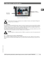
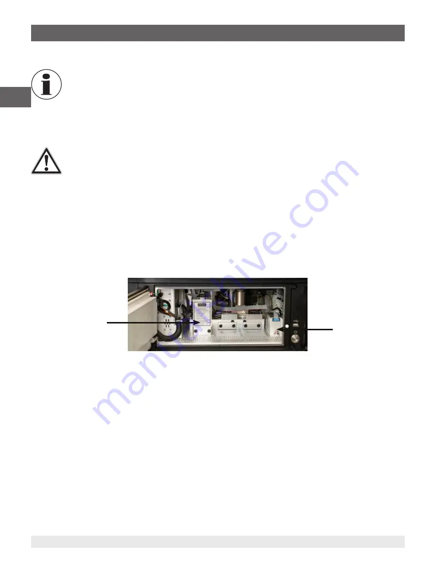
3. With the door open, you will see the pilot pneumatic transducer and an optional barometric reference. Remove the ribbon
cable from each of these sensors by grabbing the connector and lightly pulling it off the transducer port.
4. Use a 3/16" hex key to remove the two black bolts that hold the pilot sensor in place. There are two O-rings located
between the sensor and the manifold. Ensure that these O-rings remain attached to the manifold within the CPC8000-HC.
Remove the optional barometric reference transducer with the thumb screw. If the screw is too tight to remove by hand, a
small slotted screwdriver may be used.
5. To replace or reinstall these transducers, install each in the reverse order as the removal process.
Figure 8.2.3-A CPC8000-HC Front View
• CPC8000-HM Hydraulic Module
1. Vent the system by placing the controller in Vent mode. Then turn off the power.
2. Beginning with the 4 inner screws, remove all 8 screws from the front panel of the CPC8000-HM with a 4mm hex tool.
3. Once the screws are removed, the black panel will be free and can be removed. With the panel removed there will be
either 1 or 2 transducers visible.
4. Remove the ribbon cable from the transducer(s) by grabbing the connector and lightly pulling away from the transducer.
5. For cleanliness, use a paper towel or rag and place it beneath the transducer pressure connection.
6. Using two wrenches, place one on the transducer fitting and the other on the tube fitting to loosen the pressure port
connection. Fluid will drip from this port as the fitting is loosened.
7. Remove the two cap screws that hold the transducer to the baseplate using a 3mm hex drive wrench.
8. If a second sensor is installed, follow steps 5-7 for removal.
9. To replace or reinstall these transducers, install each in the reverse order as the removal process.
8. Maintenance and Recalibration
Pilot Transducer
Optional Barometric
Reference

