background image

8

Electromechanical trim tabs

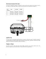
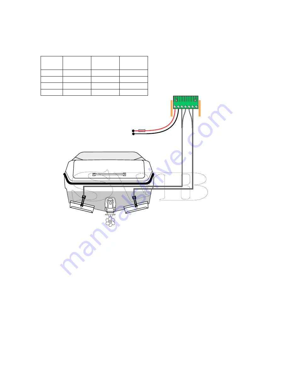
Connect the starboard actuator to terminals 5 and 6 and the port actuator to terminals 3 and 4,
according to the figure that follows. Verify the connection later on and change it if necessary.

ACS

marking

Lenco

Lectrotab

Ultraflex

3

Black (port)

White (port)

Black (port)

4

White (port)

Black (port)

White (port)

5

Black (stbd)

White (stbd)

Black (stbd)

6

White (stbd)

Black (stbd)

White (stbd)

10...30V dc (+)

(-)

15A(F)

1 2 3 4 5 6 7

3/4

5/6

Ignition key

Terminal 7 may be connected to the ignition key run position. If the ignition key is connected, retraction
will take place when switching off the engine. Without the ignition key connection, retraction will take

place after a delay when the boat has come off the plane.

Supply voltage

Connect a red wire to the boat’s main circuit breaker through a fuse. Connect a black wire to the

battery's negative (-) terminal. Minimum 2.5 mm2 (14 AWG) is recommended.

Summary of Contents for ACS R/RP

Page 1: ...ACS R RP Attitude Control System User s manual Mente Marine Vaasa Finland info mente marine com www mente marine com ...

Page 2: ...5 Auto Manual mode 5 Installation 6 Drill the holes 6 Connection 7 Hydraulic trim tabs 7 Electromechanical trim tabs 8 Ignition key 8 Supply voltage 8 Calibration 9 Verify connection 10 Usage 11 Attitude setting 11 Fine adjustment 11 Adjusting gain 12 Retraction 12 Shut down 12 Specifications 13 Troubleshooting 14 Indicators 14 Supply voltage 14 Warranty policy 15 2014 Mente Marine All rights rese...

Page 3: ...marine com Symbols and abbreviations ACS Attitude Control System LED Light Emitting Diode Security Switch off the main circuit breaker or put the ACS into manual mode before lifting or transporting the boat Should the automatics engage during transport the trim tabs may be damaged Product disposal The WEEE Directive requires the recycling of waste electrical and electronic equipment ...

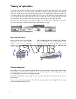
Page 4: ...the trim tabs Roll and pitch axes Both ACS R and ACS RP automatically adjust the boat to the optimum attitude in the roll axis eliminating heeling This is especially important for small and fast boats ACS RP automatically adjusts the boat to the optimum attitude in the pitch axis improving visibility and also enabling speeds in the semi planing range It also improves the hole shot Owners of large ...

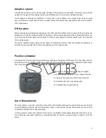
Page 5: ...ration is activated but suspended for the time being because of the slow speed Position estimation ACS shows the trim tab position estimation by lighting an indicator LED for each trim tab When a tab is extended the lit up indicator LED moves downwards No additional sensors are needed and ACS shows the trim tab position estimation for all types of trim tabs after calibration Light sensor Optimum v...

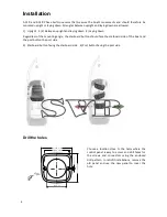
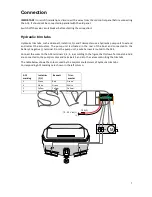
Page 6: ...ting angle the starboard button should face the starboard side of the boat and the port button the port side 5 Starboard button facing the starboard side 6 Port button facing the port side Drill the holes 50 mm 2 66 5 mm 2 62 80 0 mm 3 15 Choose a location close to the helm where the control panel is easy to access and drill holes for the screws and connectors using the enclosed drill pattern In r...

Page 7: ...e rear of the boat and connected to the battery s negative terminal From the pump unit a wire harness is routed to the ACS Connect the wires to the ACS terminals 3 4 5 6 according to the figure that follows Terminals 5 and 6 are connected to the pump s motor and terminals 3 and 4 to the valves controlling the trim tabs The table below shows the colours used by the major manufacturers of hydraulic ...

Page 8: ...e stbd Black stbd 6 White stbd Black stbd White stbd 10 30V dc 15A F 1 2 3 4 5 6 7 3 4 5 6 Ignition key Terminal 7 may be connected to the ignition key run position If the ignition key is connected retraction will take place when switching off the engine Without the ignition key connection retraction will take place after a delay when the boat has come off the plane Supply voltage Connect a red wi...

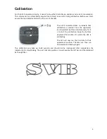
Page 9: ...t calibration is needed Press the uppermost and lowermost buttons simultaneously for 4 s to start the calibration Keep the buttons depressed for another 8 s while the ACS is calibrating The ACS will now run the trim tabs to their uppermost position The tabs are then run downwards and back up again This calibration may take up to 60 seconds and should not be interrupted After completion the indicat...

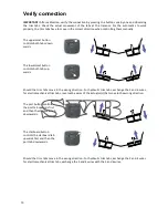
Page 10: ...s both tabs up wards Should the trim tabs move in the wrong direction For hydraulic trim tabs exchange the 5 and 6 wires for electromechanical trim tabs reverse the wires of the actuator s that move in the wrong direction The port button controls the port tab upwards first and then the starboard tab downwards The starboard button controls the starboard tab upwards first and then the port tab downw...

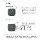
Page 11: ...a certain direction Press more times for a greater change Press and hold the auto button for 4 s to store the new setting in memory Now if the speed is reduced automatic control is suspended and the AUTO indicator starts to blink The functionality is then temporarily interrupted to avoid deflecting the tabs at too low a speed The automatic mode is re entered every time you go out until the ACS is ...

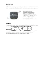
Page 12: ... setting with the uppermost and lowermost buttons The three indicator LED s in the middle show the setting Then press the left and right buttons again for 4 seconds to store the setting Retraction Retraction prevents fouling of the actuators ACS automatically retracts the trim tabs when the boat has been off the plane for a while If terminal 7 has been connected to the ignition ACS will not retrac...

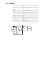
Page 13: ...15 40 feet Tab type detection Automatic Gain Automatic adapts to the boat type Size 80 77 5 10 mm Protection by enclosure IP 68 Operating temperature 10 85 C Storage temperature 40 85 C Supply voltage 10 30 V dc Maximum output current 18 A When tabs activated Current consumption 0 02 A When idle Approvals CE Compliance with EMC regulations The CE marking assures that this product complies with the...

Page 14: ... to ground L3 Supply voltage During a fraction of a second when starting a trim tab motor the current is much higher than normal and the supply wires fuseholder and battery should be in a good condition This is important when replacing mechanical switches with electronic equipment Check the voltage supply by manually operating the trim tabs If the supply is weak the ACS will restart and flash all ...

Page 15: ...rer If there is no representative of the manufacturer in your country send the equipment to the manufacturer with postage prepaid In this case it will take a considerable length of time before the equipment can be returned to you owing to the complicated customs procedures required If the equipment is covered by warranty repairs will be made and parts replaced free of charge and the equipment will...

Page 16: ...Copyright Mente Marine Elektro Navigation Schick Co GmbH Siemensstr 35 25462 Rellingen Tel 04101 301 01 Fax 04101 301 333 info ferropilot de www ferropilot de ...

Reviews: