26
Chapter 4 • Connection
User Manual FSK700-2 / FSK700-2SX
Place the cables inside the Key Safe in a way that operating the locking half cylinder(s) does not
damage the cables. Fix the cables to the Connection Board using the cable tie included in the
accessory kit of the Key Safe, see Fig. 15 above.
4.6
Typical connection diagram of a fire detection control panel and the Fire Bri-
gade Key Safe
The connection between the controlling and monitoring device and the Fire Brigade Key Safe is to
be made continuously, as well as preferably in-wall, or protected by other means. Also see the
advice on page 20 and onwards in chapter 4: "Connection".
4.6.1
Connection diagram of a system comprising fire detection control panel,
Series FSK700 Key Safe, Key Safe Controlling and Monitoring Device AD900-1,
and Power Supply Unit NT700-1
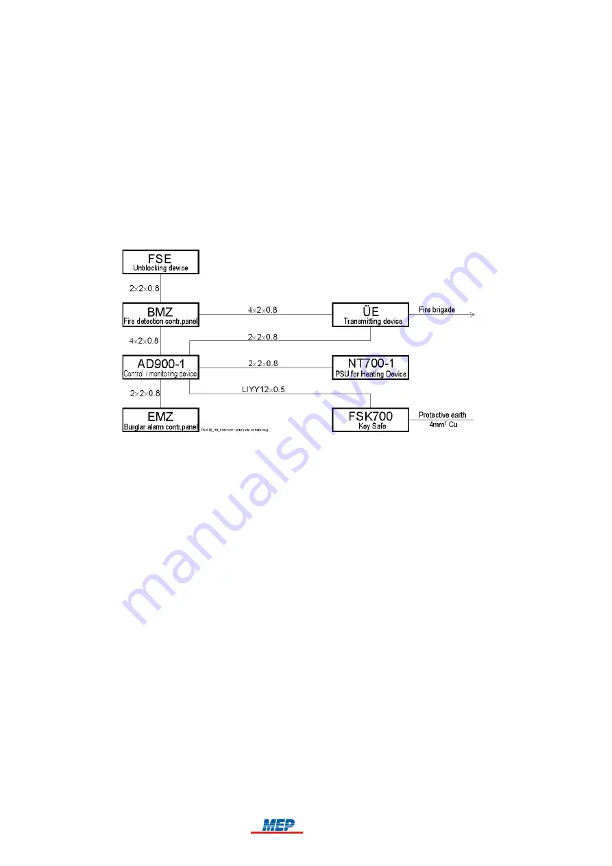
Fig. 17:
Typical example connection diagram for connecting a fire detection control panel to
- Series FSK700 Fire Brigade Key Safe,
- Key Safe Controlling and Monitoring Device AD900-1,
- transmitting device,
as well as optional devices
- Unblocking Device FSE/PHZ900-1,
- Power Supply Unit for Heating Device NT700-1
- burglar alarm control panel
Cables such as fire detector cables J-Y(St)Y n
×
2
×
0.8 or functional endurance cables JE-H(St)H
n
×
2
×
0.8 E30 can be utilised. The actual dimensioning of the cables is to be determined by
on-site requirements.
4.6.2
Connection diagram of a system comprising fire detection control panel,
burglar alarm control panel, and Fire Brigade Key Safe
The example shows
the unlocking of the Fire Brigade Key Safe by the confirmation signal from the corresponding
transmitting device, activated by fire alarm, as well as
sabotage alarm by the Key Safe Controlling and Monitoring Device AD900-1, either via the
burglar alarm control panel, or alternatively, directly alerting the security company.
HB_FSK700_1020_9161690_Englisch_D.odt / 1022 D / AN9161690
ZN62163/38/26
26
Summary of Contents for Fire Brigade Key FSK700 Series
Page 2: ......


