background image

1--3

3

Introduction and technical specifications

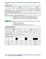
CUTTING SPEEDS

1st Slow Speed

mt/min

36

2nd Fast Speed

mt/min

72

All models can be equipped with the Inverter, an optional device, which offers

a range of speeds comprised between

20 and 90 mt/min

As the machine is

predisposed for the Inverter, it can be installed by the client or factory

pre--installed on request made during the ordering procedure.

BAND SAW

Rated size

mm

2950 x 27 x 0,9

Max/min blade length

mm

2960÷2940

Blade height

mm

27

Blade width

mm

0,9

Band saw tension

bar/kg

70 / 900

When choosing the cutting tool, if its dimensions do not correspond to those

included in the “Rated size” section, check that the dimensions at least fall

within the admissible max/min specifications.

RATED ELECTRICAL POWER

Head spindle motor

kW

1,8/1,5

Electric coolant pump motor

kW

0,06

Max installed power

kW

1,86

WORKING PRESSURE MODEL MA (Automatic Vice)

Max. working pressure for opening/closing vice

Bar

6

Air consumption for a complete cycle

Nl/min

1,34

The “air consumption” value refers to standard conditions (temperature 0

°

and

pressure 1.013 bar, i.e. density 1.3 x 10

--3

Kg/l) where 1 Kg/min. = 772 Nl/min.

LUBRICANT/COOLANT FLUID AND OIL

Oil for blade tensioner unit

V L

0,5

Oil for transmission box

capacità Kg

0,32

Oil for optional Cut Control System cylinder

capacità Lt.

0,7

Lubricant/coolant fluid (oil concentration 5---6%)

capacità Lt

13

VICE

Vice max. opening

mm

285

Warning

Attention

N.B.

Summary of Contents for SHARK 282

Page 1: ...USE AND MAINTENANCE MANUAL YEAR OF MANUFACTURE ______________ SHARK 282 EN...

Page 2: ......

Page 3: ...61045 Pergola PU ITALIA Tel 072173721 Fax 0721734533 Hereby declares that the bandsawing machine Machine model Serial number Year of manufacture SHARK 282 is in specification with the following direct...

Page 4: ......

Page 5: ...9 Electromagnetic compatibility 3 9 Machine installation 4 1 Packaging and storage 4 1 Anchoring the machine 4 4 Minimum requirements 4 4 Check list 4 5 Balancing the cutting head 4 6 Connection to th...

Page 6: ...bleeding the cylinder Cut Control System optional 7 2 Topping up the head cylinder 7 2 Bleeding the head cylinder 7 3 Vice 7 4 Vice play adjustment 7 4 Cutting head 7 5 Blade tensioner slide play adju...

Page 7: ...with positive rake from 9 to 10 degrees 9 8 Set 9 8 Standard or splayed set 9 8 Undulated set 9 9 Alternating grouped sets 9 9 Alternating set 9 9 Blade selection table relating to cutting speed and d...

Page 8: ......

Page 9: ...ials such as stainless steel light alloys aluminium copper and bronze at high speed and with high precision Its high cutting capacity combined with the possibility of making inclined cuts from 60 left...

Page 10: ...commences its downstroke the speed of which can be adjusted using the control valve head downstroke speed regulator located on the control panel The head performs the cutting operation once the cut h...

Page 11: ...se included in the Rated size section check that the dimensions at least fall within the admissible max min specifications RATED ELECTRICAL POWER Head spindle motor kW 1 8 1 5 Electric coolant pump mo...

Page 12: ...ion in air cooled machines at an ambient temperature of 40 C according to CEI 2 3 and IEC 85 the allowable overtemperature is 100 C where 100 C represents the allowable DT The machine is supplied with...

Page 13: ...1 5 5 Introduction and technical specifications PACKED WEIGHT Wooden cage and pallet kg 70 Wooden pallet kg 20 1700 1000 1900...

Page 14: ...MEP S p A 1 6 6 Use and maintenance manual SHARK 282 Dimensions MACHINE INSTALLED Work table height mm 870 Weight kg 440 900 700 470 410 550 170 1800 1830 870 1315...

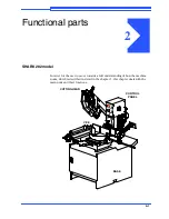
Page 15: ...In order for the user to move towards a full understanding of how the machine works which is described in detail in the chapter 5 this chapter deals with the main units and their locations CUTTING HEA...

Page 16: ...e work table and its cutting stroke is manually guided by the operator Motor Head joint pivot Blade guide heads Blade guide head plate Handgrip Handwheel Transmission box Vice The vice is the unit tha...

Page 17: ...al interference with the unit In order to remove the panel from its mounting the main switch has to be shifted to 0 OFF which automatically cuts off the electrical supply Control panel Main switch Pan...

Page 18: ...ual SHARK 282 Base On opening the door in the base you will find the air treatment unit optional extra only on versions with MA automatic vice and the drawer with the coolant complete with electric pu...

Page 19: ...all the machine s controls The instructions warnings and accident prevention standards in this manual must be respected without question by all those concerned The following definitions are those prov...

Page 20: ...e also avoiding any blinding light concentrations Reference standard ISO 8995 89 Lighting in work environments CONNECTIONS Check that the power supply cables and pneumatic feed systems comply with the...

Page 21: ...ed Always disconnect the power supply to the machine before carrying out any maintenance work whatsoever including in the case of abnormal operation of the machine Before starting cutting operations s...

Page 22: ...is cutting Do not use blades of different sizes to those recommended in the machine specifications When cutting very short pieces make sure that they are not dragged behind the support shoulder where...

Page 23: ...n applied to the SHARK 282 band saw Reference standards MACHINE SAFETY H EEC MACHINES DIRECTIVE 2006 42 CE H EEC directive no 2004 108 CE EMC Electromagnetic Compatibility H EEC Directive No 2006 95 C...

Page 24: ...he workpiece in position must be brought to within 2 3 mm of the workpiece 5 2 1 6 4 3 Electrical equipment In accordance with Italian standard CEI 60204 1 April 1998 derived from European Standard EN...

Page 25: ...e pushbutton the actuator must be rotated 45 After the emergency situation has been resolved the machine must be reset 2 Automatic thermal magnetic cutout switch with thermal magnetic relay the machin...

Page 26: ...dBA as that actually fluctuating over the same period of time This calculation is made automatically by the integrator noise meter The measurements are taken every 60 seconds in order to obtain a sta...

Page 27: ...ent that is contaminated by disturbances of defined magnitude The following text contains a list of the applied standards and the results of the electromagnetic compatibility testing of machine model...

Page 28: ...m dBuV m Result Enclosure 30 230 230 1000 40 47 Complies Immunity H CEI EN 61000 6 2 2000 Electromagnetic Compatibility EMC Generic standard on immunity Part 6 2 Industrial Environment The EUT is deem...

Page 29: ...following ways 1 on a pallet with straps and heat shrink plastic 2 on a pallet with straps heat shrink plastic and a wooden crate In both cases for correct balancing the machine must be handled using...

Page 30: ...shrink wrapped must not be stacked two high and machines pallettized and crated must not be stacked three high To install the machine first remove the packing paying particular attention not to cut an...

Page 31: ...hrink covering 4 remove the straps 5 remove nails from pallet securing planks and remove planks 6 remove the front panel and insert fork tines 3 4 5 6 To locate the machine in the workplace the machin...

Page 32: ...e BASE 12 mm 920 mm 480 mm 704 5 mm 12 mm 704 5 mm Minimum requirements For the machine to function correctly the room in which it is to be installed must satisfy the following requirements H power su...

Page 33: ...sing device speed switch emergency device thermal magnetic overload cutout minimum voltage relay voltage drop protection 24 V low voltage plant n Blade protection behind and below blade guide heads n...

Page 34: ...d to balance the cutting head weight Using a 10 mm wrench tighten the screws until the distance between the first coil of the spring and the bracket is 8 mm Connection to the compressed air supply MA...

Page 35: ...EUTRAL CONNECTION FOR 4 CORE WIRE SYSTEMS WITH NEUTRAL S L2 T L3 PE GND R L1 When using systems with a neutral wire special care must be taken when connecting the blue neutral wire in that if it is co...

Page 36: ...nge switch operate the jog button on the manual head control lever if all the above operations have been carried out correctly the blade motor will start up and the blade will start rotating Ensure th...

Page 37: ...begin with a description of the pushbuttons and other components on the control panel Description of the control panel The components of the SHARK 282 control panel are shown in the diagram below Each...

Page 38: ...device has three protection systems against power failure When there is a power failure the electrical devices are all shut down instantly shutting down the machine and preventing automatic restoring...

Page 39: ...manual control of the blade motor Microswitch Operating lever The microswitch is enabled when the machine is not in emergency state In compliance with the relevant existing standards voltage is 24V an...

Page 40: ...d movement is facilitated by perfect balancing of the head weight thanks to the traction force exerted by the two return springs located at the back of the machine Also the grip on the head control le...

Page 41: ...ng the work piece in the Automatic Vice MA version If the machine is equipped with the Automatic Vice optional device MA the opening and closing of the vice is performed by means of the manual valve s...

Page 42: ...the figure below and rotate in a clockwise direction the vice is now free to slide back and forth to the required position Once positioned release the lever to lock the vice in place Rapid translatio...

Page 43: ...al section of the workpiece so that only the part of the blade required to make the cut is actually exposed Position the workpiece on the work table in proximity to the blade downstroke trajectory and...

Page 44: ...lected is right for the kind of piece to be cut that all protections are in place and correctly locked the level of lubricant coolant and that the electropump is activated that the blade downstroke sp...

Page 45: ...ardness etc Grip the head control lever and start the blade rotating by pressing the microswitch on the handgrip the downstroke speed of the head is manually controlled by the operator The motor start...

Page 46: ...version the vice is opened using the open close button or by manually turning the vice handwheel If the machine is equipped with the Cut Control System make sure that the function selector switch is p...

Page 47: ...rod Clamp the piece in the vice if the machine is the MA version bring the vice manually to within 2 3 mm of the workpiece close the vice using the special open close button on the base of the machin...

Page 48: ...imity of the material to be cut when you reach a distance of approx 10 mm select function type Semi automatic or Dynamic and then press microswitch on the handgrip to start up blade rotation The opera...

Page 49: ...the vice is positioned to the left of the 0 cutting slot slacken the turntable lock release lever Pull the eccentric pin knob towards you 0 reference stop and rotate slightly to raise it The 0 45 and...

Page 50: ...t is in the upper position to avoid blade collision with the moving jaw on the clamp Relock the turntable lock release lever Make the cut in the required operating mode following the preliminary safet...

Page 51: ...slightly to raise it swing the head from left to right until it is positioned at the required angle as indicated by the graduated scale on the turntable relock the turntable lock release lever make t...

Page 52: ...collision with the blade downstroke Following the same procedure described above for 45 cuts to the left now position the head for 45 cuts to the right slacken the turntable lock release lever pull th...

Page 53: ...ts making up the machine giving information useful in carrying out repair and maintenance operations This chapter will also enable the user to order replacement parts with no risk of misunderstanding...

Page 54: ...the way in which they have been drawn up Each sheet of the project contains a box which gives the following information The numbers indicate the columns into which the entire drawing is divided Indica...

Page 55: ...er the dot identifies the column on that page example 11 8 indicates that the wire continues on page no 11 in column 8 This symbol identifies the wire with its relative number and colour The pages fol...

Page 56: ...andard EN 60204 1 D2 Letter codes used to designate the type of component LETTER TYPE OF COMPONENT EXAMPLES IDENTIFICATION OF THE APPLIANCE A Complex units Laser Maser Regulator A B Transducers conver...

Page 57: ...All or nothing timed relays timers KA KL KM KP KR KT L Inductors reactors Inductor Stop coil Reactor I M Motors M N Analogue intgrated circuits Operational amplifiers Hybrid analog digital appliances...

Page 58: ...onic pipes semiconductors Electronic pipe Gas discharge pipe Diode Transistor Thyristor V W Transmission lines wave guides antennas Conductor Cable Bar Wave guide Wave guide directional coupler Dipole...

Page 59: ...6 7 51 Diagrams exploded views and replace Standardised Wiring Diagrams CENELEC Standard...

Page 60: ...MEP S p A 6 8 52 Use and maintenance manual SHARK 282...

Page 61: ...6 9 53 Diagrams exploded views and replace...

Page 62: ...MEP S p A 6 10 54 Use and maintenance manual SHARK 282...

Page 63: ...6 11 55 Diagrams exploded views and replace...

Page 64: ...MEP S p A 6 12 56 Use and maintenance manual SHARK 282...

Page 65: ...6 13 57 Diagrams exploded views and replace...

Page 66: ...MEP S p A 6 14 58 Use and maintenance manual SHARK 282...

Page 67: ...6 15 59 Diagrams exploded views and replace...

Page 68: ...MEP S p A 6 16 60 Use and maintenance manual SHARK 282...

Page 69: ...6 17 61 Diagrams exploded views and replace...

Page 70: ...MEP S p A 6 18 62 Use and maintenance manual SHARK 282...

Page 71: ...6 19 63 Diagrams exploded views and replace...

Page 72: ...MEP S p A 6 20 64 Use and maintenance manual SHARK 282...

Page 73: ......

Page 74: ...A 6 22 65 Use and maintenance manual SHARK 282 Exploded views This part of the manual contains detailed exploded views of the machine which can help to gain a deeper knowledge of how it is made Motor...

Page 75: ...A DIAM 8 NR 4 000 010 7605 RONDELLA DIAM 10 NR 4 000 010 7891 VITE TCEI 8 X 16 NR 4 000 010 7963 VITE TE 8 X 25 NR 4 000 010 7975 VITE TE 10 X 25 NR 4 000 019 1706 HP 2 2 5 2 4P V 380 B14 FC90L NR 1 0...

Page 76: ...MEP S p A 6 24 67 Use and maintenance manual SHARK 282 Front flywheel assembly 282...

Page 77: ...000 010 7491 GRANO VCE PUNTA PIANA 10 X 60 NR 1 000 010 7603 RONDELLA DIAM 6 NR 7 000 010 7606 RONDELLA DIAM 12 NR 1 000 010 7764 SPINA ELASTICA DIAM 6 X 20 NR 4 000 010 7767 SPINA ELASTICA DIAM 6 X...

Page 78: ...MEP S p A 6 26 69 Use and maintenance manual SHARK 282 Motor flywheel assembly 282...

Page 79: ...IAM 4 NR 1 000 010 7603 RONDELLA DIAM 6 NR 1 000 010 7605 RONDELLA DIAM 10 NR 1 000 010 7830 VITE BUTON 5 X 10 NR 4 000 010 7850 VITE TCEI 4 X 8 NR 2 000 010 7852 VITE TCEI 4 X 12 NR 1 000 010 7854 VI...

Page 80: ...MEP S p A 6 28 71 Use and maintenance manual SHARK 282 Cutting head cover 282...

Page 81: ...LA DIAM 4 NR 2 000 010 7850 VITE TCEI 4 X 8 NR 2 000 010 7990 VITE TSPEI 4 X 8 NR 2 000 010 7993 VITE TSPEI 5 X 12 NR 4 000 016 0250 COPERCHIO ARCHETTO NR 1 000 016 1224 PIASTR FIX INTER SICUR COPERCH...

Page 82: ...MEP S p A 6 30 73 Use and maintenance manual SHARK 282 Vice assembly 282...

Page 83: ...A DIAM 8 NR 2 000 010 2372 CHIOCCIOLA BRONZO 45 NR 1 000 010 7203 DADO M6 NR 7 000 010 7427 GRANO VCE P CIL 8 X 12 NR 1 000 010 7454 GRANO VCE P CON 8 X 8 NR 1 000 010 7456 GRANO VCE P CON 8 X 16 NR 5...

Page 84: ...MEP S p A 6 32 75 Use and maintenance manual SHARK 282 Base assembly 282...

Page 85: ...20 NR 2 000 010 7972 VITE TE 16X60 NR 1 000 010 7988 VITE TE 12 X 60 NR 2 000 013 0177 PIEDISTALLO NR 1 000 016 0164 RACCOGLITORE ACQUA ARCHETTO NR 1 000 022 0321 PASSACAVI 12 INC MM 2 NR 1 000 022 03...

Page 86: ...MEP S p A 6 34 77 Use and maintenance manual SHARK 282 Control panel...

Page 87: ...BUTON 5 X 10 NR 10 000 010 7893 VITE TCEI 8 X 20 NR 4 000 016 0708 QUADRO COMANDI LVD NR 1 000 022 0211 RACCORDO RAPIDO SEM PG 13 5 NR 2 000 022 0234 PRESSACORDONE 3246 NERO PG 13 5 NR 2 000 022 0244...

Page 88: ...MEP S p A 6 36 79 Use and maintenance manual SHARK 282 Handgrip 3OUT3 SHARK 282...

Page 89: ...000 010 7409 GRANO VCE P CIL 8 X 10 NR 1 000 010 7700 SPINA CILINDRICA DIAM 4 X 24 NR 1 000 010 7800 VITE AUTOFILETTANTE 2 9 X 15 NR 3 000 022 0515 MICROINTERRUTTORE V 21 1C6 NR 1 000 025 0691 SERIE G...

Page 90: ...MEP S p A 6 38 81 Use and maintenance manual SHARK 282 Fixed work table and turntable 282...

Page 91: ...R DIAM 30 NR 1 000 010 7204 DADO M8 NR 5 000 010 7206 DADO M12 NR 1 000 010 7208 DADO M16 NR 2 000 010 7480 GRANO VCE PUNTA PIANA 8 X 30 NR 2 000 010 7481 GRANO VCE PUNTA PIANA 8 X 35 NR 2 000 010 749...

Page 92: ...MEP S p A 6 40 83 Use and maintenance manual SHARK 282 Optional Cut Control System...

Page 93: ...0 010 7830 VITE BUTON 5 X 10 NR 6 000 010 7860 VITE TCEI 5 X 15 NR 2 000 010 7870 VITE TCEI 6 X 16 NR 2 000 010 7871 VITE TCEI 6 X 20 NR 2 000 010 7923 VITE TCEI 10 X 25 NR 2 000 010 7976 VITE TE 10 X...

Page 94: ...MEP S p A 6 42 85 Use and maintenance manual SHARK 282 Supplementary pneumatic vice 282...

Page 95: ...04 ATTACCO A GOMITO 8X1_4 CL6521 NR 3 000 043 0205 INNESTO RAPIDO 1 4GHIOTTO13_A NR 1 000 043 0206 ATTACCO A ESAGONO 4X1_8CL6511 NR 6 000 043 0228 RIDUZIONE 4 1_4 NR 2 000 043 0290 ATTACCO ESAGONO 8X1...

Page 96: ......

Page 97: ...the system by an air treatment unit which if so calibrated regulates the pressure at about 6 Bar irrespective of the pressure in use in the factory circuit The pressure can in any case be set should...

Page 98: ...is low First the cylinder head is brought to the FCTI Head Up Limiter position so that the oil level in the compensation tank see photograph below can be checked using the rod If the rod upper ring l...

Page 99: ...the hydraulic circuit cause the head to stutter in down phase When this happens bleed the circuit as follows position the head at FCTI using a 10 mm open wrench slacken the bleed valve until oil exits...

Page 100: ...uts on the grub screws using a hexagonal key to hold the screws still open the vice to its full extension adjust the slight pressure exerted by the grub screws on the gib starting with the first two i...

Page 101: ...play which develops over a period of time between the blade tensioner slide and the slide gibs the grub screws separating the gibs from the slide must be adjusted as follows remove the blade from the...

Page 102: ...ished whenever needed to ensure correct operation of the unit To replenish the blade tensioning cylinder follow the steps illustrated in the figures below When the piston protrudes from the blade tens...

Page 103: ...nel screw on the filler cap using the handwheel tension the blade to 70 Bar 900 Kg The machine enters emergency status if the blade tension is too slack A pres sure contact pressure switch disables bl...

Page 104: ...hat determines its downstroke to change this setting two hexagonal spanners must be used one to keep the nut in position and the other to tighten and loosen the stop screw If the machine is equipped w...

Page 105: ...lexure caused by the vertical action of the cutting force These buttons are fitted on both the front and rear heads and need no adjustment Blade steady button Blade guide head Blade guide plates The p...

Page 106: ...e tension using the handwheel open the front blade guard by undoing the fixing screw and rotating it as illus trated in the figure below wear protective gloves when making this adjustment make sure th...

Page 107: ...un smoothly adjust the locking torque of the two grub screws with an Allen key replace any worn plates by removing the plate fixing screw repeat the above sequence of steps on the rear blade guide hea...

Page 108: ...nce operator safety and extend the tool s service life The cutting tool should in any case be replaced when poor cutting performance starts to affect productivity The tool changeover procedure is desc...

Page 109: ...guide head make sure the back of the blade is facing the flywheel stop and that the teeth along the lower part of the blade are inclined towards the head pivot Make sure there is a small amount of pla...

Page 110: ...d adjacent to the blade resting on the work surface Position the square on the cleaned work surface and rest it against the blade close to the right vice jaw at a point where the blade teeth do not pr...

Page 111: ...t right angles to the fixed vice jaw is described below To make orthogonal adjustments at 0 use a workshop goniometer or a simple 90 square Operation sequence lower the head position the goniometer or...

Page 112: ...the eccentric pin tighten down the grub screw and remount the knob lock the turntable using the lever To adjust the 45 and 60 fixed points you will need a workshop goniometer or an instrument that can...

Page 113: ...ice jaw and blade once you have identified the degree of error adjust the pins by gripping the pin with an Allen key and slackening the lock nut with a normal wrench this done adjust the depth of the...

Page 114: ...p A 7 18 104 Use and maintenance manual SHARK 282 To adjust the blade to 60 degrees left proceed as described above for a 45 degree angle this time however adjusting the stop indicated in the drawing...

Page 115: ...prevents premature wear to the blade which due to excessive friction with the edge may crack Slacken the blade tension and open the cutting head cover slacken the grub screw and using a mallet tap the...

Page 116: ...of this adjustment is to ensure that the back of the blade remains about 1 mm from the edge of the wheel during rotation To adjust slacken all the locking screws on the flywheel and manually move it i...

Page 117: ...n safety as well as for the safety of other personnel and in the interests of machine productivity H check that his own work and that of the other operators of the machine always complies with the rel...

Page 118: ...rations to carry out on the machine are as follows remove all swarf from the machine preferably with a non fibrous cloth empty the swarf drawer this is located on the right side of the base top up the...

Page 119: ...n the bottom of the water tank and the electropump filter check oil level in the CCS optional hydraulic cylinder Chapter 7 Maintenance of working parts In maintenance work on the SHARK 282 special att...

Page 120: ...and drain to top the oil up if necessary Below there is a short list of synthetic oils for permanent lubrication BP Energol SG XP220 KLUBER Syntheso D220EP ESSO Glycolube Range 220 IP CT614 SHELL Tive...

Page 121: ...K 282 it is important to select the correct type of blade for the material to be cut This chapter explains the limitations and specific applications of the different types of blades Cutting speed Stan...

Page 122: ...rature Range EN 50178 For warehouse storing from 25 C to 65 C For operating purposes from 10 C to 40 C Max altitude 1000mt with no derating Supply single phase 200V 15 to 240V 10 three phase 200V 15 t...

Page 123: ...h penetration H soft materials aluminium alloys soft bronze etc also require a coarse tooth pitch Saw tooth pitch The choice of teeth per inch therefore depends on various factors H the size of the se...

Page 124: ...pends on the material thickness Therefore large section solid or thick walled materials s 5 mm can be cut at high speeds providing there is sufficient swarf removal from the blade thin walled material...

Page 125: ...ure so that neither the saw teeth nor the work piece material in the cutting zone overheat Furthermore there must be a sufficient quantity and pressure of lubricant coolant to remove swarf from the cu...

Page 126: ...M42 C Mn Si W Mo V Ni Co Al HRC Cr 0 47 0 75 0 22 1 00 1 00 0 12 0 52 0 08 45 50 0 85 0 25 0 30 4 15 6 37 5 00 1 92 64 66 1 07 0 25 0 20 3 75 1 50 9 50 1 15 8 00 67 69 HRC 67 68 HRC 45 50 HRC 65 66 H...

Page 127: ...ge sections and diameters Variable pitch These blades have groups of teeth having different pitches and as a consequence have various tooth dimensions and differing relief angles These are also availa...

Page 128: ...toothing type is the most suitable for cutting large dimension pipes and profiles including large sections as well as for cutting solid sections up to the machine capacity limit Pitches available 3 4...

Page 129: ...set is used with very fine teeth for cutting thin pipe walls and small section profiles from 1 to 3 mm Alternating grouped sets These are groups of teeth angled to the right one straight tooth then a...

Page 130: ...6 4 6 4 6 4 6 3 4 3 4 3 4 3 4 3 4 3 4 3 4 3 4 3 4 3 4 3 4 3 4 3 4 3 4 60 70 50 60 15 20 15 20 75 90 80 90 25 40 70 80 80 90 S10 10S30 30S50 50S80 80S120 120S230 Dimensions of the cutting section S mm...

Page 131: ...845 En 58 E En 56 A En 58 G A 1 A 2 En 36 4360 50 A 3706 1 2 3 En 20 A En 31 1022 1035 1040 1010 1015 1060 1065 5135 5145 4135 3135 4315 8645 W 1 L 6 T 1 1310 316 304 410 309 S D 3 M 13 3310 3315 AST...

Page 132: ...120 M 19 150 M 28 060 A 40 060 A 96 070 M 55 080 A 40 080 A 62 1717 CDS 110 708 A 37 708 M 40 735 A 50 534 A 99 817 M 40 311 typu 6 i 7 BD 2 BD 3 BS 1 304 S 15 304 C 12 316 S 16 317 S 16 XC 18 XC 38 H...

Page 133: ...able you to follow a methodical procedure for solving any problem Troubleshooting blade and cutting problems PROBLEM PROBABLE CAUSE SOLUTION Blade scored or scratched Widia inserts chipped or worn Rep...

Page 134: ...nd downstroke speeds or clean surface Cutting speed too high The teeth slide on the material without cutting reduce cutting speed Head downstroke speed too slow The band saw runs over the material wit...

Page 135: ...45 right and left by means of the appropriate screws Perpendicularity of the blade to the work surface Check and realign the blade guide heads then adjust the blade using the appropriate screws so tha...

Page 136: ...l may have altered surface areas such as oxides or sand or subcooled inclusions in the section These areas are much harder than the blade and will cause the teeth to break scrap or clean these materia...

Page 137: ...m downwards so as to bring the blade steady buttons up against the back of the blade Sections with large thickness variations The cutting speed and downstroke speed must be chosen to suit the most cri...

Page 138: ...ring cutting check the vice jaws and clamping pressure Widia inserts positioned incorrectly Adjust inserts position especially the width since blade thickness can exceed the manufacturer s declared to...

Page 139: ...rts If worn the inserts can score the blade weakening it even to breaking point If the inserts are too far apart the blade will whip striking both the inserts and the material Replace or adjust Insuff...

Page 140: ...put fuse Spindle motor will not turn Electrical power supply Check the phases the cables the plug the socket Also check that the motor connections are in place Motor contactor Check input and output p...

Page 141: ...place Filter Clean The pressure gauge does not give blade tension pressure Oil level Top up oil level in blade tensioner cylinder Blocked connection Check for blockages Broken If damaged replace Cutti...

Page 142: ...connections Replace if defective Lock valve Check for impurities preventing correct functioning Replace if defective Regulator Check that input and output pipes are free of kinks and obstructions Spr...

Page 143: ...the front of the machine base The machine is set up for the passage of pneumatic pipes for positioning the pneumatic selector and for the maximum pressure valve on the air inlet on the back of the bas...

Page 144: ...ng holes on the slide and reinsert the dowel and collar H connect the pipes and couplings from the kit and check that they are working Blade The blades that can be used on this machine include H 2950x...

Page 145: ...meter hole in the back of the base near the existing three holes H Drill a 22 mm diameter hole in the back face of the control panel being careful not to damage the electrical equipment inside H Drill...

Page 146: ...MEP S p A 11 4 136 Use and maintenance manual SHARK 282 H form the connections as shown in the layout below SH 280...

Page 147: ...tres This device is used to measure the length of the pieces to be cut To fit this accessory on the machine H screw the support for the rod marked off in millimetres to the existing seating on the dis...

Page 148: ...e 1500 6000 mm H K60R K100R roller table for discharge side 1500 6000 mm H To fit the roller loading platform on the loading side the machine has a bar support arm that one end of the roller way can b...

Page 149: ...he load bearing strength of the roller table both during feeding and discharge The steps which should be followed to assemble it are illustrated below disconnect the table from the adapter on the disc...

Page 150: ...right side of the slideway install adaptor A fixing the plate to the fixed platform after having removed the bolts and fit the support under the plate resting it on the machine base install adaptor B...

Page 151: ......

Page 152: ......

Reviews: