ID: D03935
REV: C
11
3.4.
PLACING THE HEATER
When installing and placing the heater these instructions and the regulations of the local
authorities have to be considered.
Place the heater on a level and incombustible material so that the foundation
reaches 500 mm further off than the heater itself.
Minimum protection clearance from combustible materials and constructions:
-
min. 1500 mm in front of air outlet, if the construction is protected using
incombustible materials clearance can be reduced to min. 750 mm.
-
horizontally min.500 mm.
-
above min 1000mm.
When placing the heater indoors secure adequate fresh combustion air to the
burner.
I
T IS NOT ALLOWED TO PLACE THE HEATER IN A SPACE WITH NEGATIVE
PRESSURE
Do not place the heater into premises where explosive or combustible fumes are
present.
Protect the heater from rain, water spray or dripping water.
DO NOT USE HEATER WITHOUT THE BURNER COVER.
If there is a air duct connected to the heater:
-
air duct must be out of incombustible and heat resisting material.
-
clearance from combustible materials has to be min 100 mm.
The heater has to be connected into a outgoing chimney.
The chimney has to comply with the regulations and instructions given by the local
authorities.
Distance to oil tank min. 3 m.
The fuel tubes or pipes have to be approved for this kind of service.
3.5.
PRIOR TO START-UP
Before starting the heater, check the following:
1. safe clearance and ventilation.
2. proper condition
3. oil tank and pipes.
4. the fuel is not frozen.
5. smoke flue connection.
6. voltage and fuses.
NOTE! The oil burner is adjusted at the factory to maximize the starting and burning
result. If the conditions change (e.g. long smoke flue) and the flame is not burning
properly, readjust the burner air damper position.
Summary of Contents for thermox K110-2
Page 2: ......
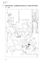
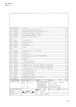
Page 18: ...ID D03935 REV C 16 6 VARAOSAKIRJA RESERVDELSKATALOG SPARE PART BOOK 6 1 K55 ...
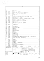
Page 19: ...ID D03935 REV C 17 ...
Page 20: ...ID D03935 REV C 18 ...
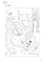
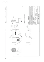
Page 21: ...ID D03935 REV C 19 6 2 K110 ...
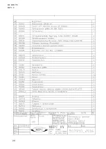
Page 22: ...ID D03935 REV C 20 ...
Page 23: ...ID D03935 REV C 21 ...
Page 24: ...ID D03935 REV C 22 ...
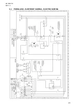
Page 25: ...ID D03935 REV C 23 6 3 PIIRIKAAVIO ELEKTRISKT SCHEMA ELECTRIC SCHEMA ...
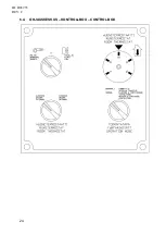
Page 26: ...ID D03935 REV C 24 6 4 OHJAUSKESKUS KONTROLLBOX CONTROL BOX ...
Page 27: ......


