background image

MERCEDES-Benz  

Service 

___________________________________________________________________ 


Mercedes-Benz AG 

 Omnibus Product Division 


Status September 2003 (EvoBus-Service / AFT) 


Natural Gas Engine: M 447 hLAG


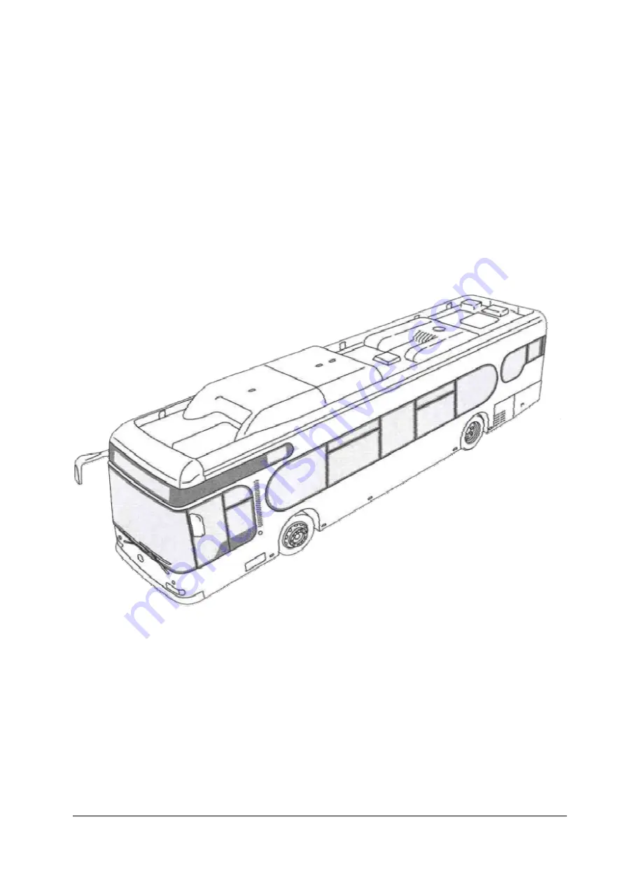
In Mercedes-Benz City Bus  
 

Click bus for index 


The 

EGM

 engine control unit 


Summary of Contents for M 447 hLAG

Page 1: ...___________________________________________________ Mercedes Benz AG Omnibus Product Division Status September 2003 EvoBus Service AFT Natural Gas Engine M 447 hLAG In Mercedes Benz City Bus Click bus...

Page 2: ...arking and distinguishing individual components When ordering spare parts the part numbers should always be taken from the spare parts documentation This training document resulted as part of the temp...

Page 3: ...xibly Programmed Controller FR FahrzeugRegelung Vehicle Control FSP FehlerSPeicher Fault Memory H Leitung High Leitung CAN High Line HW HardWare IBIS Integriertes Bord InformationsSystem Integrated On...

Page 4: ...un fuel cut off SAS 38 2 5 6 Switch on conditions for gas injection 38 2 6 Ignition 40 2 6 1 Firing angle in starting mode 40 2 6 2 Firing angle determination in idling mode 40 2 6 3 Firing angle dete...

Page 5: ...ressure 63 4 1 20 Atmospheric air pressure 64 4 1 21 Oil pressure 65 4 1 22 Throttle valve target position 66 4 1 23 Throttle valve actual position 66 4 1 24 Lambda target value 66 4 1 25 Lambda actua...

Page 6: ...____________________________________________ Status September 2003 EvoBus Service AFT Page 6 of 83 5 5 Safety precautions when working on EGM 79 6 Appendix 80 6 1 Pulse width modulated signal 80 6 2 O...

Page 7: ...ctuation 31 Switch on conditions for boost pressure control 32 Switch on threshold for boost pressure control 33 Switch off threshold for boost pressure control 33 Overview gas mass calculation in nor...

Page 8: ...ssure regulator is heated with the engine coolant A partial icing up of the pressure regulator is quite normal Complete icing up could lead to the failure of the pressure regulator Next the CNG relaxe...

Page 9: ...harge air pressure is controlled for the respective operating point by the EGM For this purpose the EGM actuates the electropneumatic converter EPW of the wastegate The lambda broadband probe is mount...

Page 10: ...st gas LLK Mixer EGM engine control TEMIC Engine coolant Heat exchanger CNG 8 bar CNG Filter CNG Tank approx 30 to 200 bar CNG 8 bar Woodward Injektor block ND valve T P Engine coolant ITT pressure re...

Page 11: ...s indicated at the top of the sticker This data record number should always be specified when purchasing a replacement The EGM engine control unit is an electronic spark ignition engine control unit f...

Page 12: ...e Gas mass calculation Air mass Injection Angle for start of gas delivery Gas injection angle Lambda target value Lambda correction factor Gas mass Target engine torque FR y Engine protection y Idling...

Page 13: ...culation of gas mass to be injected With the knowledge of the air mass and taking the target lambda and the lambda correction value into account the gas mass to be injected is calculated in the next s...

Page 14: ...an estimated boost pressure The available engine torque is limited as a function of the engine speed 5 Engine protection camshaft emergency running mode If the camshaft signal fails the engine is ope...

Page 15: ...ature is intended to reduce the maximum permissible engine torque at excessively high charge air temperatures The value for the reduction of the available engine torque is calculated with the engine r...

Page 16: ...a hysteresis of 1 C is implemented before the warning buzzer request due to an excessively high coolant temperature is cancelled again when the temperature drops When the warning buzzer is requested...

Page 17: ...is entered This limit pressure check takes place cyclically every 40 ms An active overpressure fault is first reset in the engine state Engine stopped with the engine stopped If the boost pressure on...

Page 18: ...M must estimate the air mass in the combustion chambers to continue engine operation This is only possible in the engine intake mode and therefore the wastegate of the exhaust gas turbocharger is open...

Page 19: ...haft signal fails before system synchronisation the engine control switches into the crankshaft emergency running mode In the crankshaft emergency running mode the so called dual ignition two cylinder...

Page 20: ...is required for system synchronisation and when the crankshaft signal fails If the crankshaft signal fails camshaft emergency running mode the crank angle is determined based on the camshaft signal Vi...

Page 21: ...bda correction factor with the corresponding fault memory entry 0775 Control deviation too great or d the engine control has detected an implausible probe heating current with the corresponding fault...

Page 22: ...ector Measures Break in wiring Interturn fault Torque reduction 20 per failed injector pair The actuation of the corresponding injector pair is deactivated Ignition remains completely switched on all...

Page 23: ...ircuit short circuit to earth break in wiring File kd_hwd_zuendung_Fehlerdarstellung vsd Date of last change 2001 08 22 Actuation of engine control 4 3 Ignition module 5 Kl GND Battery Short circuit t...

Page 24: ...ction function can be blocked for a period of 10 seconds after start operation transition from engine state Start to Normal operation The function remains reset i e no oil pressure warnings are output...

Page 25: ...position 2 DK If the engine speed exceeds the threshold of 2 400 rpm for hard speed limitation DRB hard then the overspeed protection function also switches off the gas injection in the second step u...

Page 26: ...ervice AFT Page 26 of 83 Engine protection exhaust gas temperature Exhaust gas temperature Limitation torque Torque limitation Exhaust gas temperature Map Exhaust gas temperature Engine speed MOB Torq...

Page 27: ...ntly of the engine state the LLR can operate both in the engine state Idling and in the partial and full load operating modes Minor speed dips during load connection e g when starting off at traffic l...

Page 28: ...e engine state changes from the Normal operation state to the Engine starting state as soon as the engine speed is less than 71 rpm starter DOES NOT engage The engine state Engine starting is an opera...

Page 29: ...GM the throttle valve target position7 The electronics integrated in the throttle valve carries out the position control of the throttle valve and returns a position feedback to the EGM the throttle v...

Page 30: ...r general positioning error is detected and the fault code 8378 is entered If this fault occurs the gas injection is blocked and it is NOT possible to start the engine Exceeding of minimum maximum thr...

Page 31: ...pressure then the wastegate is closed Schematic diagram of wastegate actuation The operating pressure of the pneumatic actuator is controlled by an electropneumatic converter EPW The EGM carries out a...

Page 32: ...m Engine speed ATL controller ON Speed threshold ATL on Target boost pressure Characteristic curve Engine speed Speed threshold ATL off Target boost pressure Caracteristic curve 1 B press threshold AT...

Page 33: ...03 EvoBus Service AFT Page 33 of 83 Switch on threshold for boost pressure control Switch off threshold for boost pressure control DK Boost pressure threshold ATL on Target b press bar f speed rpm Tar...

Page 34: ...ry 40 ms An active overpressure fault is first reset in the engine state Engine stopped with the engine stopped If the boost pressure only briefly exceeds the currently permissible value the fault deb...

Page 35: ...ric mass ratio of air and the natural gas used and the lambda target value In addition the gas mass based on the variables previously named is charged as needed with warm up and dynamic enrichment Mas...

Page 36: ...tion Gas mass Air mass g stroke Gas mass uncorrected g stroke Gas injection gas mass determination in normal case File kd_gas_m_best vsd Datum 08 10 2000 Air mass Basic factor Warm up factor Limitatio...

Page 37: ...l load operation To measure the real actual lambda a lambda probe broadband probe is integrated in the exhaust system between the turbocharger and the catalyst Input variables of the lambda controller...

Page 38: ...obe becomes active and the engine is only operated further controlled lambda control OFF A substitute value of 1 2 is selected for the target lambda 2 5 5 Overrun fuel cut off SAS The overrun fuel cut...

Page 39: ...tate engine stopped Speed limitation hard speed limitation Overrun fuel cut off STOP button Zero quantity request via CAN 1 Gas cut off valve OFF ON Gas injection OFF ON Title Service EGM Gas release...

Page 40: ...ion in idling mode In the idling mode the firing angle is mainly determined by the engine speed Depending on the engine speed one firing angle is interpolated for the warm engine state and one for the...

Page 41: ...w File zue_ bersicht vsd Datum 08 08 2003 Firing angle Firing angle in starting mode Firing angle in idling mode Firing angle in partial load and full load mode Engine state Starting Engine state Idli...

Page 42: ...ption Level converter PC monitor and printer COM 1 Hand held tester K wire Block diagram overview of interfaces File ele_sch vsd Datum 29 Okt 1999 X016 Fan Vehicle control FR Starter Battery Ignition...

Page 43: ...Prop_return switching output 12 Off 19 Crank angle position sensor On 20 TDC Cylinder 1 sensor On 21 Lambda lean probe IA On 22 Knock signal 1 On 23 Knock sensor return On 24 Knock signal 2 On 25 Lamb...

Page 44: ...ttery voltage battery positive TER30 6 Battery voltage battery positive TER30 7 n c TDC_Trigger 8 Starting actuation signal TER50 On 9 Earth Battery negative TER31 10 Proportional valve supply 34 high...

Page 45: ...wer consumption ignition on engine stopped 0 2 A at U 27 V average power consumption at engine speed 500 rpm 1 7 A at U 27 V Peak power consumption without proportional output stages 10 A cyclical dep...

Page 46: ...ase of polarity reversal of supply connections short circuit current flows through ignition transformer To prevent damage to ignition transformer it must be limited to max 7 5 A with external measures...

Page 47: ...following input variables Sensor data M447hLaG Measured Variable Boost Pressure Gas Pressure Woodward Active Oil Pressure Absolute Pressure Sensor Bosch Combi Air Mass not present RV in k 10 10 3 6 1...

Page 48: ...TC in 49000 16241 7475 3808 429 241 126 89 Coolant temperature Temperature sensor data RV 1 K 1 4 C at 100 C or 1 7 C at 20 C T in C 40 20 5 10 70 90 115 130 U in V 4 9 4 71 4 41 3 96 1 5 0 97 0 56 0...

Page 49: ...arrives via the CAN bus The switching thresholds for reliable detection of the Terminal 15 voltage on connector pin 15 of the 16 pin engine connector are Control Unit Version Terminal 15 ON Terminal...

Page 50: ...2 Gas injector actuation The gas injector actuation is primarily intended to ensure that the gas injectors open reliably and the fed gas mass is transferred In contrast to PLD compliance with an exac...

Page 51: ...y opened before the end of the push phase Hold phase After the push time expires the system switches over to the holding mode with an actuation frequency of 5 kHz The suitable selection of the pulse d...

Page 52: ...r an electrical probe heater is required According to the manufacturer these new types of probes produced in planar technology do not permit charging with a heater voltage of 24 V Therefore a switchin...

Page 53: ...oing into the limitation see illustration of principle of ignition actuation To protect against continuous energising the ignition module automatically limits the primary current to approx 7 5 A and a...

Page 54: ...et value FR 1 00 rpm 9 Redundant speed Ter W FR 1 00 rpm 10 Engine speed 1 00 rpm 11 Exhaust gas temperature 1 00 C 12 Vehicle speed FR 1 00 km h 13 Coolant temperature 1 00 C 14 Gas temperature 1 00...

Page 55: ...ed See the Engine performance data of the individual output variants 4 1 3 Actual engine torque The actual engine torque is calculated from a map in dependence on the engine speed and the air mass Thi...

Page 56: ...target value FR During operation with operating speed control the Control speed target value FR is equivalent to the operating speed specification for the operating speed controller During operation o...

Page 57: ...15 or 6716 is entered In the case of a fault a fixed substitute value of 30 C is output Exhaust gas temperature sensing is only possible with control units from hardware version C2 The characteristic...

Page 58: ...gine starting engine state starting the charge air temperature is used as a substitute value In the other engine states the substitute value is 92 C If the fault debouncing time has not yet expired ho...

Page 59: ...2 seconds then the event Fault measuring range exceeded or dropped below is detected and the fault code 1115 or 1116 is entered Then the substitute value of 30 C is used as the gas temperature If the...

Page 60: ...ressure sensor is above 4 95 V or below 0 67 V for more than 2 seconds then the event Fault measuring range exceeded or dropped below is detected and the fault code 1715 or 1716 is entered Then the su...

Page 61: ...ure sensor is stored in the engine data record If the voltage of the oil temperature sensor is above 4 97 V or below 0 10 V for more than 2 seconds then the event Fault measuring range exceeded or dro...

Page 62: ...range exceeded or dropped below is detected and the fault code 1215 or 1216 is entered The substitute value of 40 C is then used as the charge air temperature If the fault debouncing time has not yet...

Page 63: ...plausibility of the boost pressure sensor in the Engine stopped engine state is checked with the signal of the atmospheric pressure sensor With the engine at a standstill the boost pressure and atmos...

Page 64: ...essure sensor is above 4 75 V or below 2 30 V for more than 2 seconds then the event Fault measuring range exceeded or dropped below is detected and the fault code 1315 or 1316 is entered A substitute...

Page 65: ...the plausibility of the oil pressure sensor in the Engine stopped engine state is checked with the signal of the atmospheric pressure sensor With the engine at a standstill the oil pressure and atmos...

Page 66: ...nds then the event Fault measuring range exceeded or dropped below is detected and the fault code 0915 or 0916 is entered A substitute value of one is used as the lambda actual value If the fault debo...

Page 67: ...too rich i e too much gas is injected possible indication of defective gas injectors or faulty air mass detection 4 1 28 Air mass The air mass is calculated from a map as a function of the boost press...

Page 68: ...ad engine state ONLY idling and partial load 2 Warning buzzer Stop lamp CAN status L line CAN status H line 1 0 3 2 5 4 7 6 00 not requested 01 requested 10 n d 11 s n a 00 not requested 01 requested...

Page 69: ...V 3 Status PV 4 1 0 3 2 5 4 7 6 00 not active 01 active 10 n d 11 s n a 00 not active 01 active 10 n d 11 s n a 00 not active 01 active 10 n d 11 s n a 00 not active 01 active 10 n d 11 s n a On natur...

Page 70: ...tatus September 2003 EvoBus Service AFT Page 70 of 83 No dec Information Bit Coding Remarks 8 Cut off valve state 1 0 00 CLOSED 01 OPEN 10 n d 11 s n a n d not defined s n a signal not available n f s...

Page 71: ...s injector sticks open gas injector does not open correctly leaks on injector block etc Failure of ignition on one or several cylinders mixture leaning due to excess oxygen Faulty signal of boost pres...

Page 72: ...minutes or by switching off Ter 15 4 3 3 Cylinder selective ignition switch off The Customer Service routine Cylinder selective ignition switch off enables the ignition of any desired cylinder to be...

Page 73: ...approx 8 bar A leak test of the gas injectors can be carried out in this way Notes The engine run on can be switched off once by starting the routine Switch off engine run on repeatable Deactivation...

Page 74: ...ing EGM 5 1 Troubleshooting The internal fault diagnosis is generally an important aid for troubleshooting so that the fault memory content should always be checked at the start of troubleshooting 5 1...

Page 75: ...___________________________________________________________ Status September 2003 EvoBus Service AFT Page 75 of 83 5 1 4 Reduced engine output Possible causes 5 1 5 Rough engine running traction inter...

Page 76: ...3 EvoBus Service AFT Page 76 of 83 5 2 Special tools Condition for testing Battery voltage 24 volts Brake pressure at least 8 5 bar Spark plug spanner w f 16 Stroboscopic lamp Socket box for 55 pin en...

Page 77: ...EGM _____________________________________________________________________ Status September 2003 EvoBus Service AFT Page 77 of 83 Remove page in hand out and replace with a copy of the wiring harness...

Page 78: ...r M 447 hLAG 185 kW M447hLAG 240 kW at 2000 rpm 1250 Nm at 1500 rpm 0 200 400 600 800 1000 1200 1400 600 800 1000 1200 1400 1600 1800 2000 2200 0 40 80 120 160 200 240 280 Torque Nm Power kW Power kW...

Page 79: ...not disconnect batteries from the vehicle electrical system with the engine running False polarity of the control unit supply e g false polarity of the batteries can lead to the control unit being de...

Page 80: ...a PWM signal The PWM signal is characterised by the frequency f and the pulse duty factor TV An example of such actuators are Gas injectors Proportional valves EPW for actuating the ATL etc Drawing pu...

Page 81: ...is only one of a large number of control units in the interconnected system of the natural gas CITARO the interconnected system of the natural gas CITARO is identical to and completely compatible wit...

Page 82: ...ning mode 14 19 20 charge air temperature 14 15 coolant temperature 14 16 dual ignition 14 19 exhaust gas temperature 15 25 gas injection 14 22 ignition 14 23 lambda lean controller probe 14 21 38 67...

Page 83: ...L Lambda actual value 66 Lambda correction factor 67 71 Lambda target value 66 Lambda probe heating current 66 O Oil pressure 65 Overview of bus systems EvoBus 81 P Performance data 55 78 185 KW 78 2...

Reviews: