Electrical Description of EGM
Status September 2003 (EvoBus-Service / AFT)
Page: 42 of 83
3
Electrical Description of EGM
3.1
System interface overview
3.1.1
Block diagram
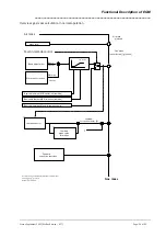
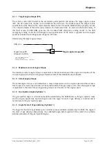
Block diagram for electrical description:
Level converter
PC
+ monitor and printer
COM 1
Hand-held
tester
K-
wire
Block diagram - overview of interfaces
File:
ele_sch.vsd
Datum: 29.Okt. 1999
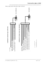
X016
Fan
Vehicle control (FR)
Starter
Battery
Ignition lock TER15, TER 50
CAN
Crankshaft/camshaft sensors
Gas injectors
n
-
Throttle valve
k
-
Service switch Start/Stop
ignition
Proportional valves
n
-
Sensors
Starter
Motorstecker (55-polig)
Vehicle connector (16-pin)


