background image

P 3

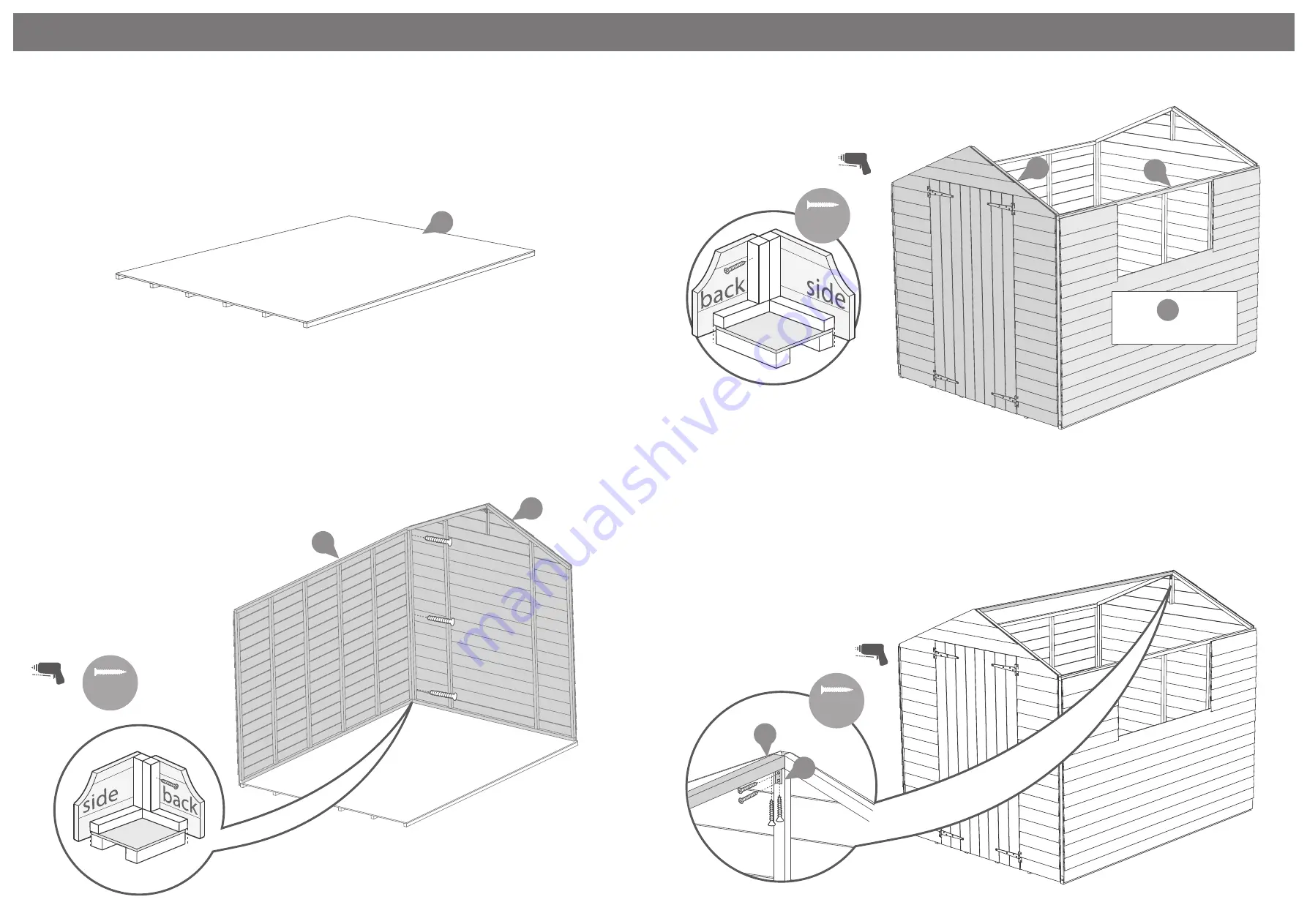
Place the floor on a firm and level base, 

ensure the base has suitable drainage free 

from areas where standing water can collect. 

See the front page for base requirments.

Step 1

5

Do not secure the building to the 

floor until the roof is fitted. Fix the 

panels onto the floor using 50mm 

screws in alignment with the floor 

joists

Fix the corners with 50mm screws 

as shown in diagram.

Position the panels so there is equal spacing 

between the floor and cladding on all 4 sides

Step 2

3x50mm Screws

Pre drill 

hole

50mm 

screw

Step 3

9x50mm Screws

Fix the corners with 50mm 

screws as shown in diagram.

1

4

Use         for no 

window buildings

3

Pre drill 

hole

50mm 

screw

Step 4

8x20mm Screws

Place the ridge bar in between the front 

and back gables. Ensure the top corners 

of the ridge bar sit flush with the top 

points of the door gable. Fix the ridge bar 

to the gable using one L bracket for each 

end.

Fix with 4x20mm screws each 

15

24

20mm 

screw

Pre drill 

hole

3

2

Summary of Contents for 01OVLPA0806DDFW-V2

Page 1: ...annually to prevent the timber from deteriorating and to waterproof it This is required to maintain the anti rot guarantee Dip Treated buildings Require a preservative treatment to protect against rot and decay and a waterproof treat ment to prevent water ingress Pressure Treated buildings Require a waterproof treatment to prevent water ingress Log Cabins Are supplied untreated and require a prese...

Page 2: ...rene QTY 2 FW ONLY PI 05 0114 18 19 21 L Bracket QTY 2 PI 07 0012 16 Capping Felt Turn Button QTY 3 PI 07 0034 20 22 15 Eaves Frame 28x28x1195mm QTY 4 F2828 1195 24 23 Door Gable QTY1 AI 01OVLPDG1707x1960 V2 Back Gable QTY1 AI 01OVLPPG1707x1974 V3 Plain Side QTY 2 NW ONLY AI 01OVLPPS2360x1567 V3 Window Panel QTY 1 FW ONLY AI 01OVLPWS2360x1567 V2 Floor QTY 1 AI 01OVLPF2350x1753 V2 Roof QTY 2 PI 03 ...

Page 3: ... diagram Position the panels so there is equal spacing between the floor and cladding on all 4 sides Step 2 3x50mm Screws Pre drill hole 50mm screw Step 3 9x50mm Screws Fix the corners with 50mm screws as shown in diagram 1 4 Use for no window buildings 3 Pre drill hole 50mm screw Step 4 8x20mm Screws Place the ridge bar in between the front and back gables Ensure the top corners of the ridge bar ...

Page 4: ...m screw Pre drill hole Pre drill hole Step 6 b Once the roof is fixed attach the building to the floor with 50 mm screws 16x 50mm Screws 50mm screw Pre drill hole 100x Tacks Felt tacks 21 22 22 21 Step 7 Cut the felt into 2 sheets at 2490mm and fix onto the roof using felt tacks as shown in diagram ensuring there is 50mm overhang around the sides Cut the capping felt to 2490mm and fix over the cen...

Page 5: ...ne sheets on top of the window cill When positioning the styrene sheets ensure there is an equal distance between them and at either side of the windows Fix the window strips to the two pieces of framing that sit alongside the outside edges of the window with 3x30mm screws for each strip Attach the three window strips at either side of the windows using 3x30mm screws each Make sure the screws ente...

Page 6: ...screws by screwing through the outside of the door into the block 8x30mm Screws 2x30mm Black Screws 4x30mm Screws b c a 13 20 14 a 13 20mm screw 30mm screw Use 5x20mm screws to fix the door strips to the right hand door Note Door Strips must be attached to right hand door Use 1x30mm black screw to fix the turn button onto the left hand door 5 x 20mm Screws 1x 30mm Black Screw Step 12 12 11 20 It i...

Reviews: