F Motor Replacement:
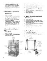
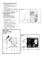
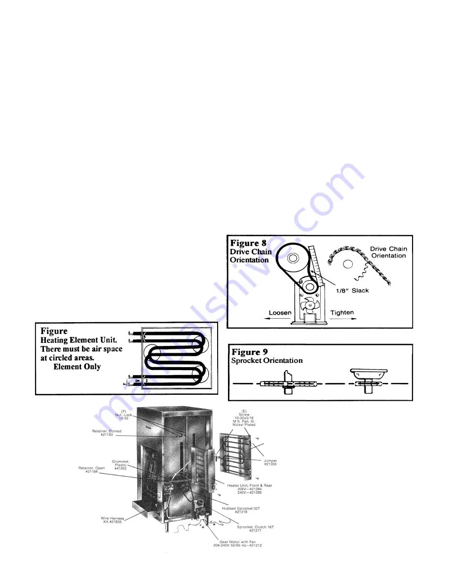
(Refer to Figure 8, 9 & 9A)
1. Remove right side panel.
2. Disconnect motor lead wire from terminal block and
conveyor speed control (and or P.C. board if your unit
contains one). Or on-off switch on C-40 only units.
3. Remove two mounting bolts from under toaster that attach
motor bracket. Slip off drive chain.
4. Lift out motor and bracket assembly and remove four
screws holding motor to bracket.
5. Using 1/16” Allen wrench, loosen Allen screws and remove
clutch sprocket from motor shaft.
6. Mount clutch sprocket on new motor shaft and mount new
motor on bracket.
7. Install motor and bracket assembly attaching with the two
mounting bolts. Do not tighten bolts.
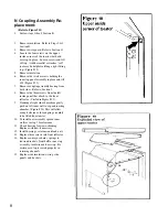
8. Mount drive chain on sprocket by sliding motor to the left
then adjust chain by sliding motor to the right (Figure #8).
Tighten bolts.
6. Slide new heater unit into place and fasten
with two screws.
7. Replace insulation.
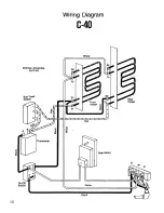
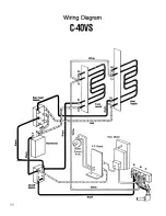
8. Reconnect wiring harness (Refer to Wiring
Diagram). Hold heater terminals with pliers.
Be sure all connections are tight and jumper
has been installed between upper heater unit
connections.
E Individual Heater Element
Replacement:
Each heater unit is equipped with two
elements.
These may be replaced individually as
follows:
1. Remove heater unit as described in Section
D.
2. Place unit on a flat surface and remove
jumper and the two screws, nuts and
retainers.
3. Bend holding tabs away from element and lift
out at an angle that will let terminal ends clear
holes.
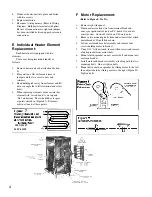
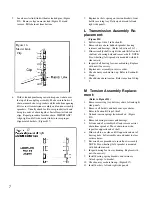
4. When replacing elements, make certain that
element with “raised bend” is on top and
“flat” on bottom. There should be air space
at points circled in (Figure #7). Elements
must not touch at these points.
7
208V-21107
240V-21109
4

