N Coupling Assembly Re-
placement:
(Refer to Figure #11)
1. Follow steps 1 thru 5 Section K.
2. Remove insulation. Refer to Steps 2 & 3
Section D.
3. Remove wire guard. Refer to Section O.
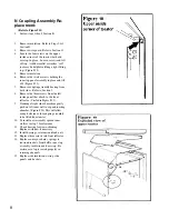
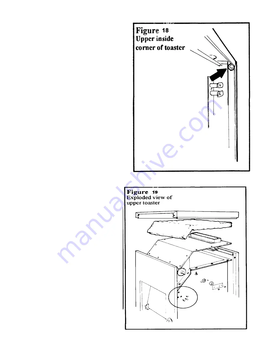
4. Locate the four screws on the upper
inside corners of the toaster that hold
case top in place. Loosen screws and lift
off top. A rubber mallet or similar “soft”
tool may be helpful in lifting a tight fitting
top. (Figure #18)
5. Remove insulation.
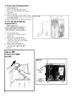
6. Remove the twelve screws holding the
inner top panel assembly in place and lift
off. (Figure #19)
7. Remove coupling assembly bearing from
both sides. Refer to Section J.
8. Remove the three screws from the left
inside panel that attach to the front
reflector. (Circled in Figure #19).
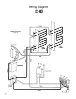
9. Standing at right side of machine gently
push on left inner wall to expand toasting
chamber. (Figure #20) This will allow
enough clearance for coupling assembly
to be lifted from toaster.
10. To install new assembly spread inner
walls as in step 9 for clearance.
11. Check bearing for wear or binding.
Replace with new if necessary.
12. Install bearings, retainers and lock nuts.
13. Replace three screws into front reflector.
14. Replace conveyor chains, springs to
tension brackets, front baffle, inner top
assembly, insulation and case top. Be
certain case top is seated properly in
retaining channels.
15. Replace side insulation, wiring, side
panels and baskets.
8

