2
INSTALLATION
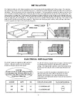
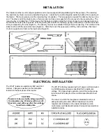
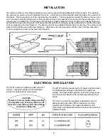
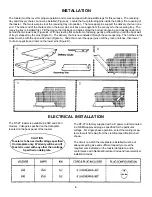
The toaster must be level for proper operation and comes equipped with adjustable legs for this purpose. The receiving
tray and delivery chute can now be installed (Figure A). Locate the four protruding pins inside the bottom front opening of
the toaster. The two lower pins lock the receiving tray into position. The two upper pins support the delivery chute on one
end. The other end of the chute rests on the lower pins so it lies at an angle from the conveyor to the receiving tray. The
receiving tray is installed first. Tilt the tray so that the back end slides along the bottom of opening and passes under and
behind the two lower pins (Figure B). With tray resting flat on bottom of opening, gently pull toward you until the back wall
of tray is stopped by the pins (Figure C). The delivery chute is now installed through the same opening. The notches in the
sides must be with the open side down (Figure A). Slide chute over the upper pins until they rest in notches, then lower
chute so opposite end rests on the lower pins (Figure D).
ELECTRICAL INSTALLATION
The RT-2T toaster is available in 208V and 240V
models. Voltage is specified on the data plate
located on the back panel of the toaster.
CAUTION
Toaster is to be used with voltage specified
On data plate only. Warranty will be void if
Toaster is used with any other than voltage
Specified on data plate.
The RT-2T is factory supplied with a 6” power cord terminated
in a NEMA approved plug as specified for the particular
voltage. For single phase operation, select the mating recep-
tacle to match the plug from the electrical specification chart
shown.
The circuit on which the receptacle is installed must be of
adequate wiring size and sufficient capacity to meet the
requirements indicated on the toaster data plate, and in
conformance with National Electrical Code and local electrical
installation codes.


