EXi-F
positive pressure smoke control system
„MERCOR” S.A. –
Specifications are subject to change without notice. Version DTR_EXIF_EN_20220516
Page
12
/ 28
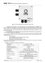
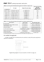
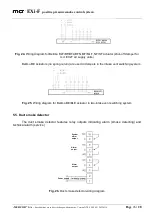
The following lights indicate pressure regulator failures and alarms:
MCR BUS 1,
MCR BUS 2,
ADAPTATION,
IN,
SENSOR.
The alarm light goes on when a failure is detected. Light off indicates correct operation. MCR
BUS 1 and MCR BUS 2 indicate failure of the communication bus connecting the system components.
Both lights ON indicate major failure of the communication bus. ADAPTATION indicates incorrect
pressure regulator adaptation, and if ON, the pressure regulator requires adaptation. IN indicates
discontinuity of the alarm line connected to DI+ and DI-. SENSOR indicates failure of one of the system
sensors.
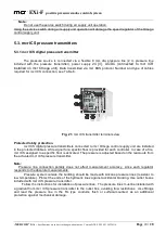
Detailed information on detected failures are available via a built-in service interface.
Other errors can be indicated by short-circuiting O and CM terminals (relay output). The
terminals are short-circuited when an error is detected.
The following lights indicate regulator status:
POWER,
STATUS.
POWER is always on when the power is supplied to the device.
STATUS is always on in standby mode (awaiting an event) or flashing to indicate fire.
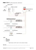
Emergency control procedure is activated by FACP signal input with specific parameters.
Omega CU requires FACP signal as a voltage free NC switch contact (contact state for operation in
standby mode). The contact should be bridged with the end of line resistor to ensure line continuity
monitoring. At standby, MMS controller awaiting for FACP signal reads zero resistance at its input and
treats it as no alarm. If the contact is opened, the controller reads the resistor resistance and executes
a program stored in its memory. If the resistance at the controller input increases to infinity, the unit
treats it as a failure, indicates the status with controller lights and transmits a signal.
After installing and checking the correct operation of all system components, the system
starts the adaptation procedure. Pressure regulator operation parameters and adaptation
procedure are performed by „MERCOR” or an authorized service centre.
The control unit cooperates with the fire control panels as per the following procedure: receive
signal to activate the fire program (hardwired signal), transmit control unit failure signal to FACP
(hardwired signal), confirm control procedure of connected devices by the control unit to FACP
(hardwired signal).
Unit inputs and outputs (all lines) are continuously monitored by the end of line resistors for
interruptions, short-circuit and time parameters of activation of all connected devices.
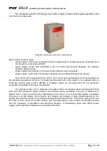
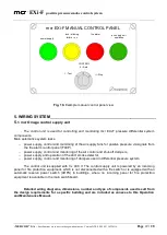
The unit door is fitted with a visualization panel with lights indicating:
power supply status (green light on - power supply on);
failure/error (yellow light off - correct unit operation);
FACP alarm (red light off - no FACP alarm);
"Reset" button (alarm reset), press and hold for
approx. 5 seconds to return to the unit's initial state (standby). No FACP signal can be
present at the alarm input(s).
All units have a "Test" button. During the test, the unit executes alarm procedure stored in its
modules/controllers for a specific fire scenario. After the test, the unit waits for 10 seconds, and
irrespective of the results sets its outputs to initial state to set the external devices in alarm standby
mode. Check each signal individually if there are several FACP alarms and related TEST buttons.


