EXi-F
positive pressure smoke control system
„MERCOR” S.A. –
Specifications are subject to change without notice. Version DTR_EXIF_EN_20220516
Page
19
/ 28
Maximum allowable positive
pressure
100 [kPa]
Measurement error
+/-1.5 [%]
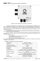
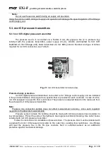
The following lights indicate the pressure transmitter alarms and failures:
MCR BUS,
PRESSURE,
IN.
MCR BUS indicates the communication bus failure. PRESSURE indicates the pressure sensor
failure. IN indicates discontinuity of the alarm line connected to DI+ and DI-.
The following lights indicate the pressure transmitter status:
POWER,
STATUS.
POWER is always on when the power is supplied to the device. STATUS is always on when
awaiting an event or flashing when indicating fire.
4.3.
Auxiliary components of mcr EXi-F system
________________
4.3.1.
Intake vent switching system
_____________________________________________
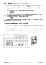
If the air inlets are at the roof level, two air inlets are required, distant from each other and
facing different direction to avoid leeward position in relation to the smoke source. Each inlet should
provide full air supply required by the system. All inlets should be protected by an independent system
of smoke control dampers (when one damper closes due to the smoke, another inlet will supply air
required by the system). The smoke is detected by the smoke detectors upstream of each damper.
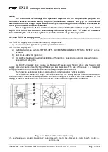
An intake vent switching system with two opposed dampers and Belimo B(L)E actuators is
used.
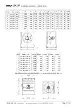
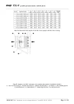
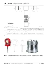
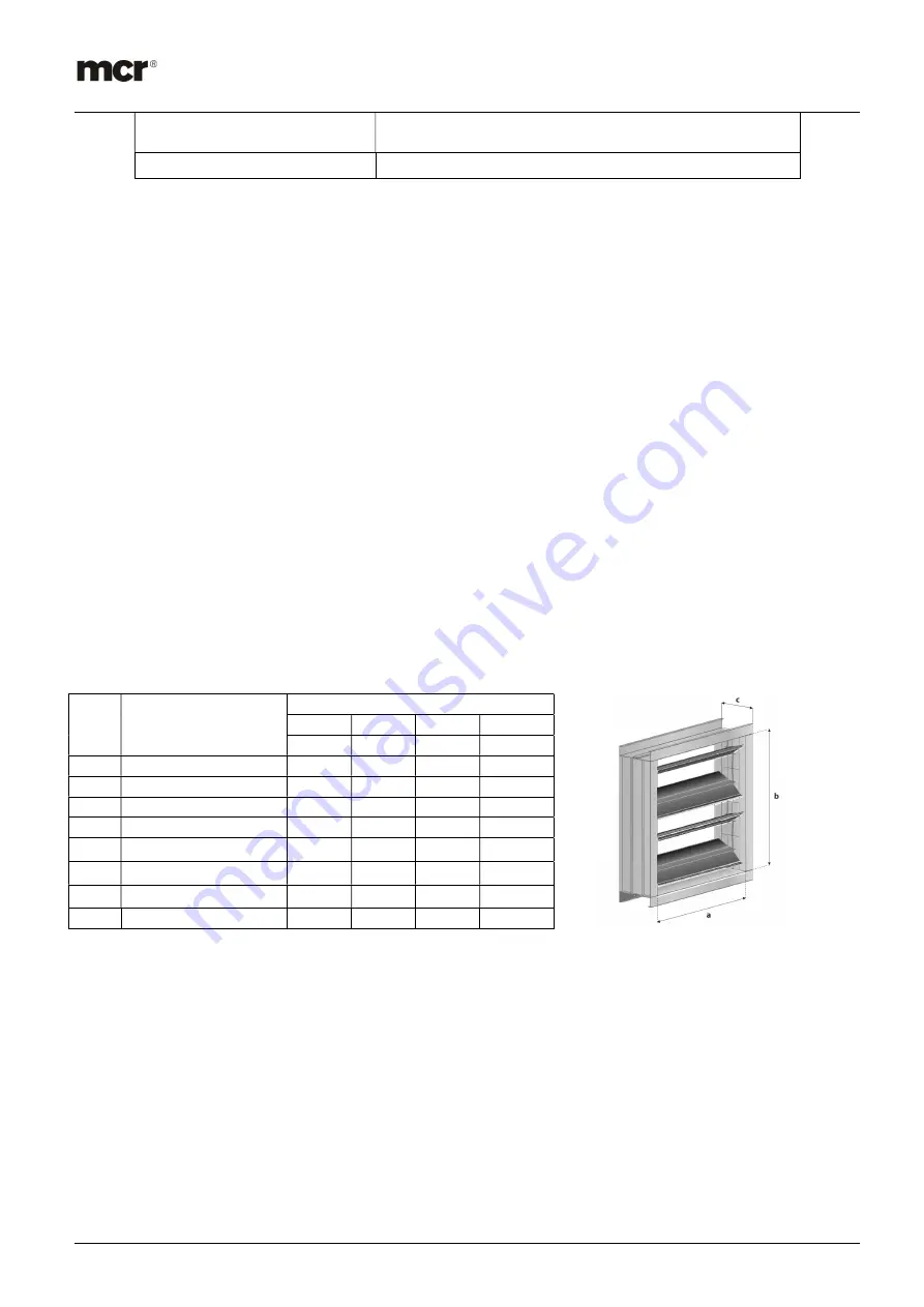
Fig. 15.
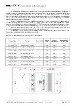
Basic dimensions of the air dampers used in two damper configuration
Item
System type
Air damper
a
b
c
weight
[mm]
[mm]
[mm]
[kg]
1
mcr EXi-F 100-1S
1100
1100
115
18.5
2
mcr EXi-F 100-2S
1100
1100
115
18.5
3
mcr EXi-F 90-1S
1100
1100
115
18.5
4
mcr EXi-F 90-2S
1100
1100
115
18.5
5
mcr EXi-F 80-1S
900
900
115
14
6
mcr EXi-F 71-1S
700
700
115
10
7
mcr EXi-F 71-2S
700
700
115
10
8
mcr EXi-F 63-1S
700
700
115
10

