EXi-F
positive pressure smoke control system
„MERCOR” S.A. –
Specifications are subject to change without notice. Version DTR_EXIF_EN_20220516
Page
21
/ 28
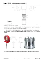
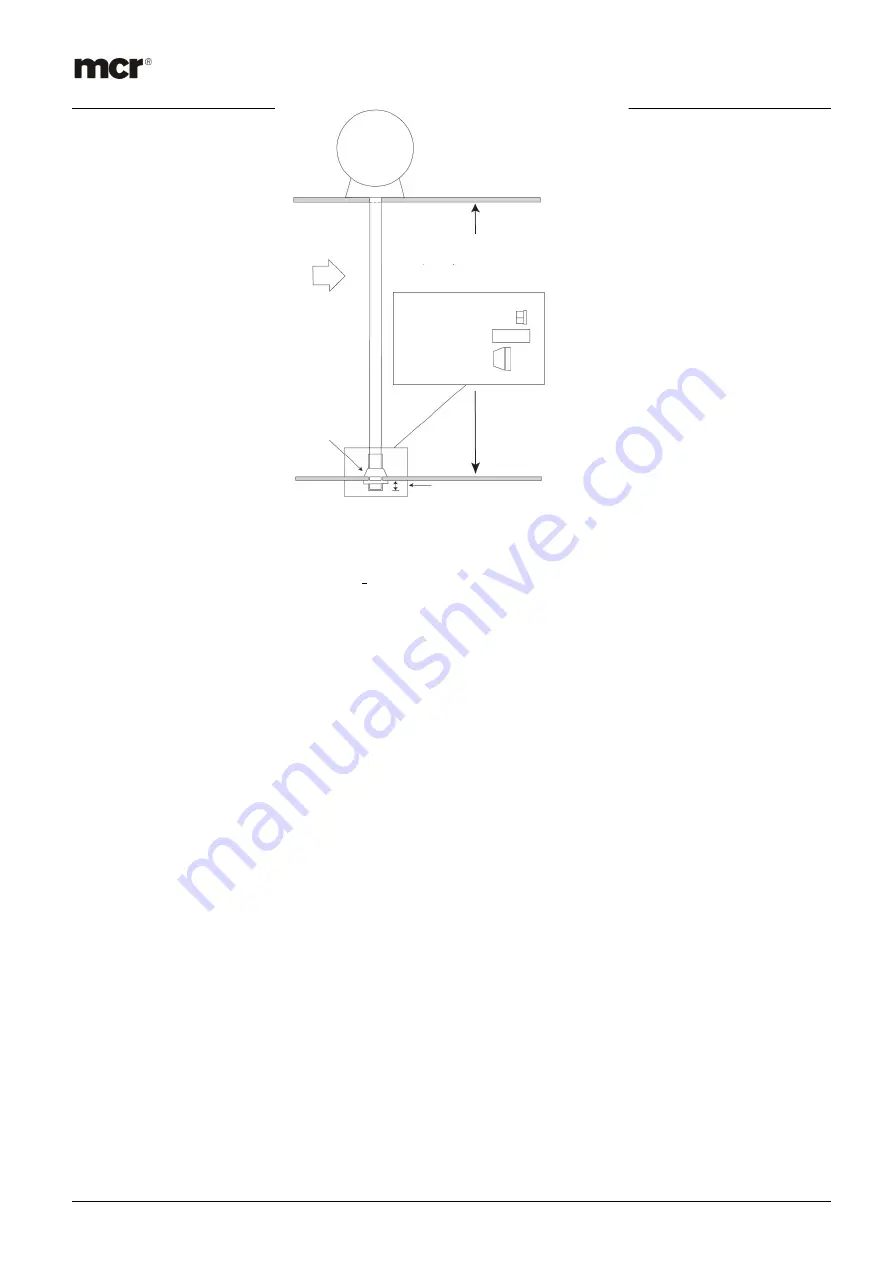
Fig. 18.
Duct smoke detector installation in the air supply duct
4.3.3.
Manual control panel (MCP)
______________________________________________
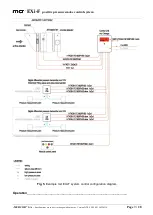
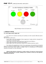
Manual control panel for remote system control using a switch located in a key-locked cabinet.
The panel allows manual air supply system activation and deactivation by a fire-fighter during any fire-
fighting operations. The panel should be located near the fire exits and easily accessible to the
rescuers. The panel indicates unit operation status:
power supply – green light ON indicates correct system operation,
failure – yellow light ON indicates system failure,
alarm – red light ON indicates alarm,
lock – blinking yellow light indicates manual lock,
air inlet fan operation - green light ON indicates air supply unit operation
Drill Ø 38 mm
hole
Venturi tube should
pass through the entire
duct.
Drill Ø 50 mm
hole
Venturi tube must not protrude over 30 mm
outside the duct wall.
Cut line to required length
Install the plug at the end of
Install the gasket at the
end.
Install the gasket.

