EXi-F
positive pressure smoke control system
„MERCOR” S.A. –
Specifications are subject to change without notice. Version DTR_EXIF_EN_20220516
Page
24
/ 28
Note:
Do not use the service switch during air supply unit operation.
Using the service switch during air supply unit operation will damage the speed regulator of the Omega
control supply unit.
5.3.
mcr ICS pressure transmitters
5.3.1 mcr ICS digital pressure transmitter
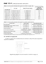
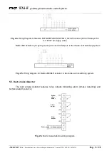
The pressure source is connected via a flexible 8 mm dia. pressure line (2 m pressure line
included with the pressure transmitter), power supply
24 [V], AC/DC (connected to mcr ICR
installed on mcr Omega unit)
. Data transmitted via mcr BUS protocol. Number and type of cables
required for mcr ICS connection, see Table 6.
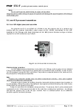
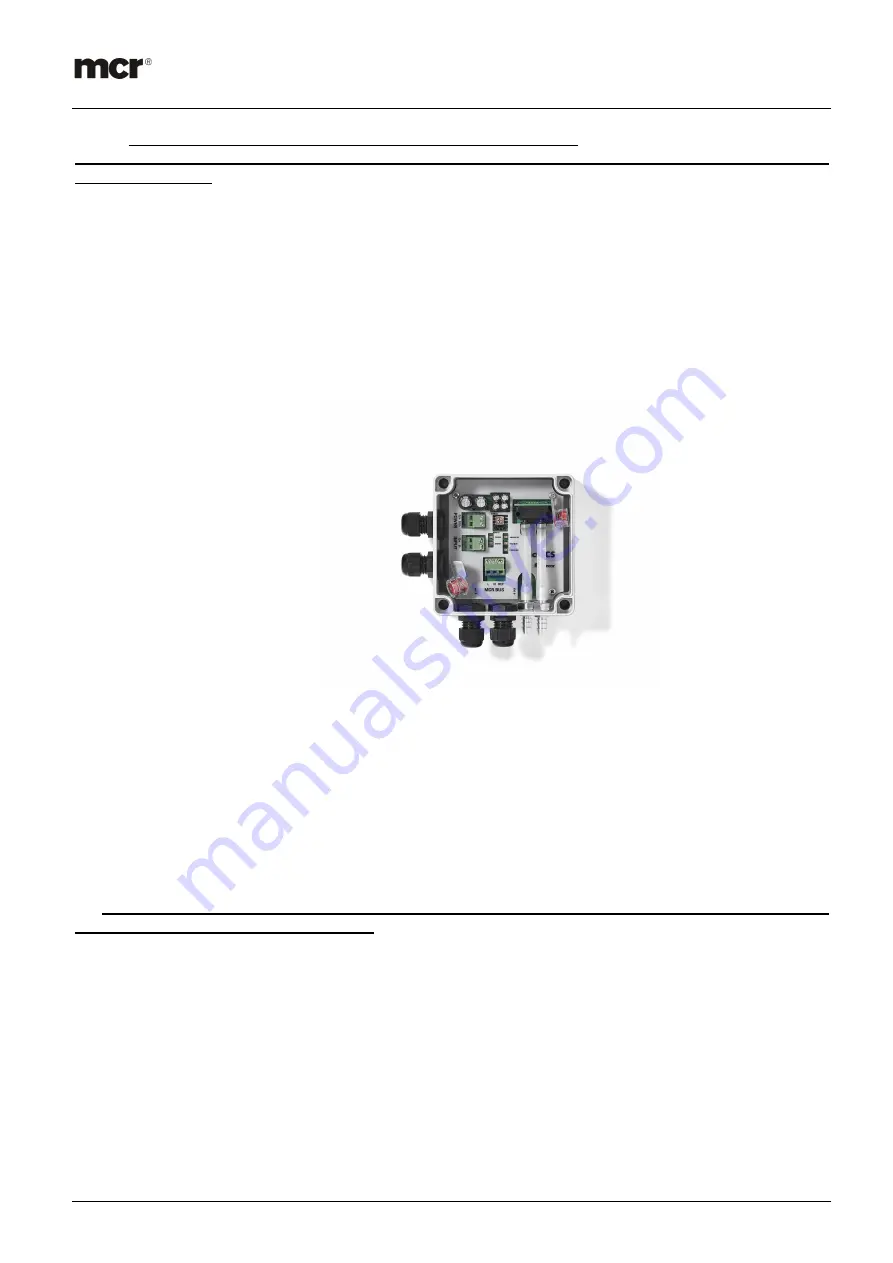
Fig. 21.
mcr ICS transmitter terminals view
Protected lobby protection.
mcr ICS digital pressure transmitters connected to mcr Omega control supply unit are installed
in the protected lobbies. A fire signal for a specific floor is provided for each controller. In case of a fire,
mcr ICS assigned to a specific floor is activated. The pressure is adjusted based on the read-outs from
the activated mcr ICS pressure transmitter.
Note:
Pressure line connection polarity does not affect measurement accuracy, since each regulator
responds to the absolute measurements.
Pressure system outside the building should be made with silicone pressure lines (resistant to
low temperature). Protect the ends of the hydraulic lines against accidental blocking. Use outlet boxes
included with mcr ICS pressure transmitter.
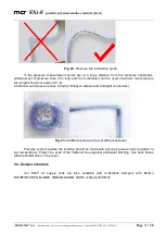
Follow the instructions for installation of pressure lines. The pressure lines must be installed with
a gradient from mcr ICS pressure transmitter to the outlet box, avoiding flow restrictions. Use fittings
and lead the pressure line in the RL type conduits, flush or surface-mounted, as an additional
protection against mechanical damage.

