Mcr WIP type multi-blade fire dampers
14/17
MERCOR SA –
the Company reserves the right to make modifications and changes.
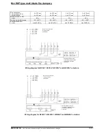
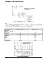
Wiring diagram for BE24, BLE24, BE230 and BLE230 actuators
Notice:
Controlling the operation of BE and BLE actuators requires connecting them to an electrical wiring system using
three-wire cables. The change of rotation direction is effected by applying supply voltage to terminal 2 or 3,
depending on the desired direction of rotation.
The position of limit switches for all actuator types applies to a potential free position.
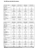
Technical data – actuators
EXBF B 001 2 ...0 N 000
EXBF A 001 2 ...0 N 000
Power supply
24 V AC ±20% 50/60 Hz / 24 VDC-10/+20%
230 V AC ±14% 50/60 Hz
Power demand:
– when putting the spring under
tension
– when in standby
7 W
2 W
8 W
3 W
Apparent power
10 VA
12.5 VA
IP rating
IP 66
IP 66
Auxiliary switch:
– activation point
2 x SPDT 6 A (3) max 250 V AC
5
°
, 80
°
2 x SPDT 6 A (3) max 250 V AC
5
°
, 80
°
Torque:
- motor
- spring
18 Nm
12 Nm
18 Nm
12 Nm
Movement time (90°C):
- motor
- return spring
150 s
≈
20 s
150 s
≈
20 s
Ambient temperature
−20 ...+50°C
−20 ...+50°C
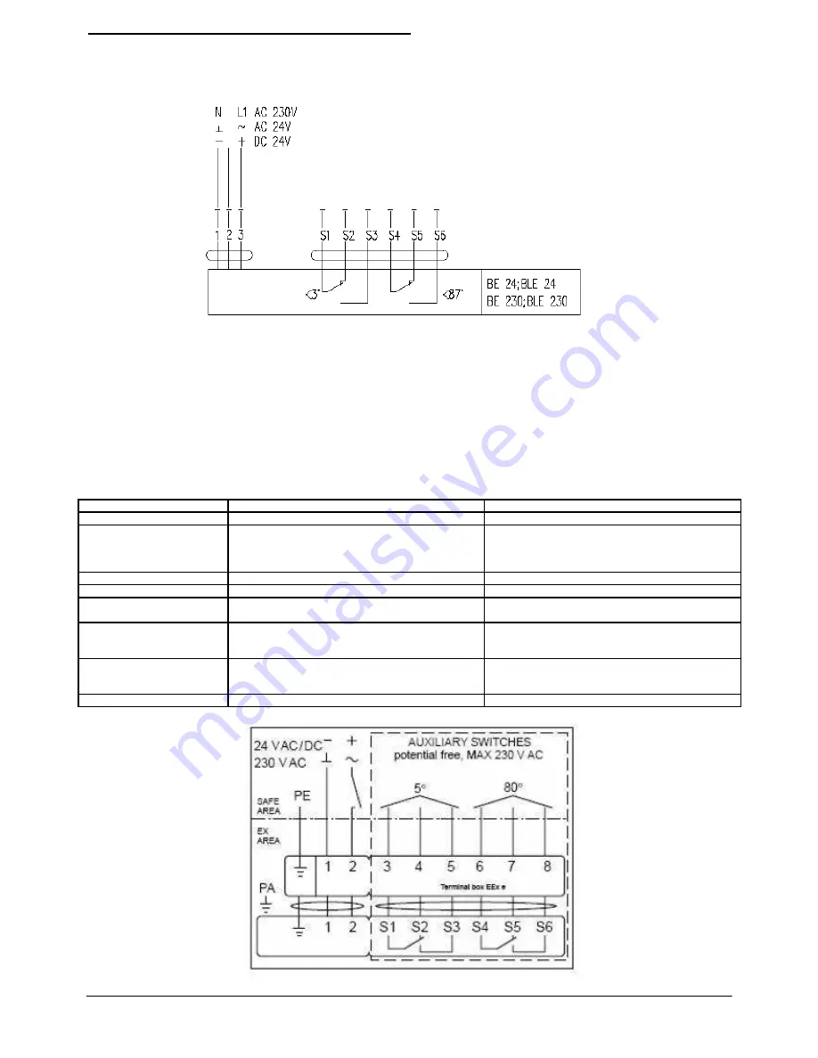
Wiring diagram for EXBF actuators
Several actuators may be
connected in parallel. Power
consumption should be
monitored.
Notice: 24 V connection
through a safety
transformer.
To disconnect the BE230 and BLE230 actuators from
the electrical wiring system (mains), a breaker switch
is required with at least a 3 mm gap between its
contacts (in deactivated state).


