5.0l / 305 cid / 5.7l / 350 cid ENGINES
SERVICE MANUAL NUMBER 24
Page 3A-70
90-861327--1 OCTOBER 1999
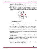
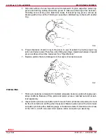
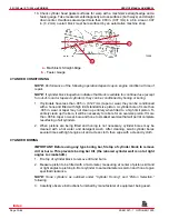
1. Assemble piston to connecting rod using piston pin remover as shown. Follow instruc-
tions supplied with kit.
72371
a
a -
Piston Pin Remover (J-24086-B)
2. Once assembled, check piston for freedom of movement (back and forth and up and
down) on connecting rod. Piston should move freely in all directions. If it does not, piston
pin bore is tight and piston / pin assembly must be replaced.
3. If a new connecting rod has been installed, mark connecting rod and cap (on side of rod
and cap with slots for connecting rod bearing tangs) with cylinder number in which it will
be installed.
PISTON RINGS
All compression rings are marked on upper side of ring. When installing compression rings,
make sure that marked side is toward top of piston.
Oil control rings are a three-piece type, consisting of two rings and a spacer.
1. Select rings comparable in size to cylinder bore and piston size.
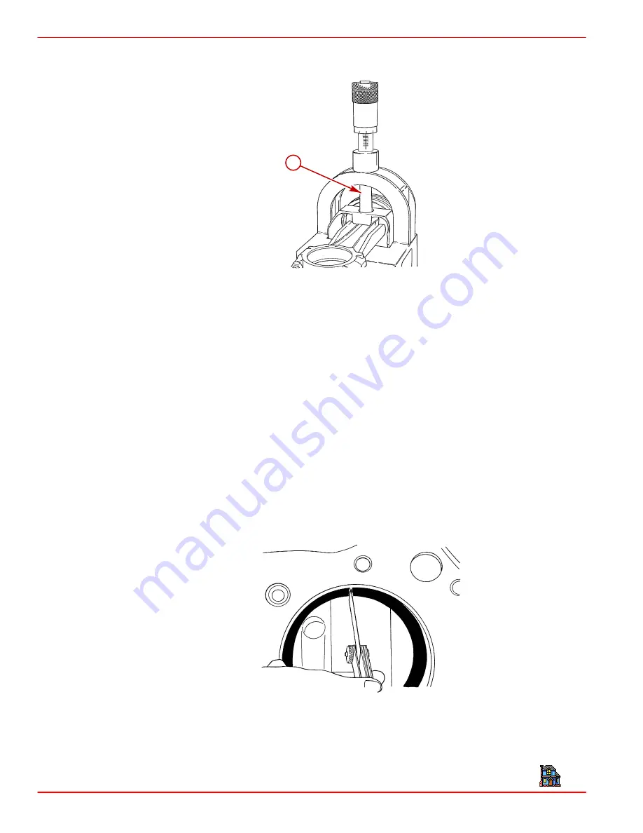
2. Slip compression ring in cylinder bore, then press ring down into cylinder bore about 1/4
in. (6 mm) (below ring travel). Be sure that ring is square with cylinder wall.
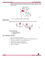
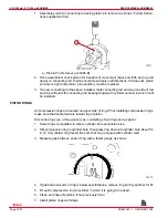
3. Measure gap between ends of ring with a feeler gauge as shown.
72372
4. If gap between ends of ring is below specifications, remove ring and try another for fit.
5. Fit each compression ring to cylinder in which it is going to be used.
6. Clean and inspect pistons, if not previously done.
7. Install piston rings as follows:
Index

