CHARGING SYSTEM
SERVICE MANUAL NUMBER 24
Page 4C-18
90-861327--1 OCTOBER 1999
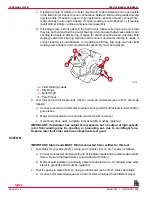
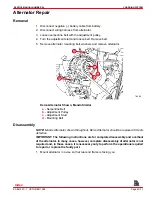
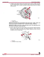
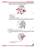
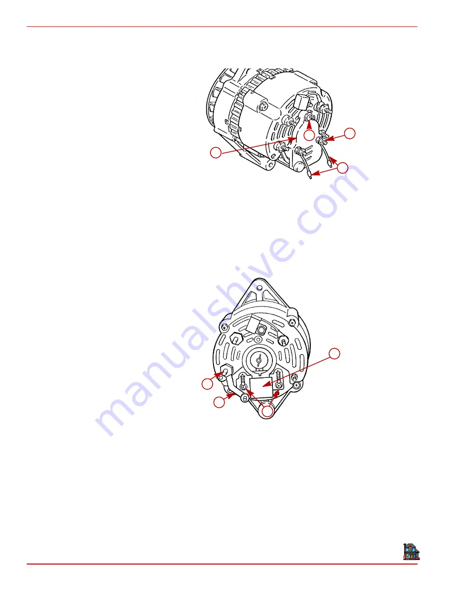
2. Disconnect regulator leads from terminals on rear end frame. Remove four nuts, Phillips
head screw and two regulator leads. Then pull regulator cover away from rear end
frame.
72963
b
d
c
a
a -
Regulator Leads
b -
Nuts (4)
c -
Phillips Head Screw
d -
Regulator Cover
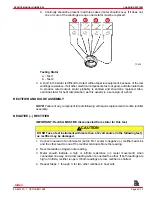
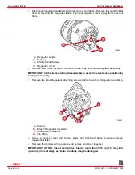
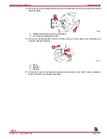
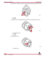
3. Remove stud cover insulator, two nuts and tie strap from brush/regulator assembly.
IMPORTANT: Scribe pieces during disassembly to assist in exact same positioning
during reassembly.
4. Remove two brush/regulator attaching screws and remove brush/regulator assembly.
72823
a
b
c
d
a -
Screws
b -
Brush / Regulator Assembly
c -
Stud Cover Insulator
d -
Tie Strap
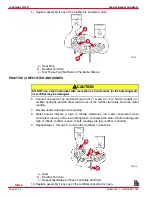
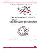
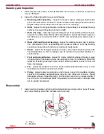
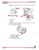
5. Scribe a mark on rear end frame, stator and front end frame to ensure proper
reassembly later.
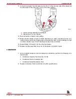
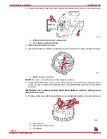
6. Remove four screws which secure end frames and stator together.
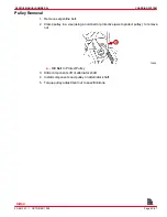
IMPORTANT: DO NOT insert screwdriver blades more than 1/16 in. (1.5 mm) into
openings (in next step), as stator windings may be damaged.
Index

