FUEL INJECTION DESCRIPTIONS AND SYSTEM OPERATION
SERVICE MANUAL NUMBER 24
90-861327 OCTOBER 1999
Page 5D-3
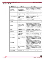
Special Tools (cont’d)
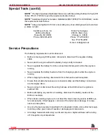
NOTE:
1
The High Impedance Multimeter that comes with the existing Outboard 2 Cycle EFI
Tester, P/N 91-11001A2 meets the requirements listed above.
NOTE:
2
Quicksilver Digital Tachometer / Multi-Meter (DMT 2000) P/N 91-854009A1, meets
the requirements listed above.
NOTE:
3
Using a test light with 100 mA or less rating may show a faint glow when test actual-
ly states no light.
Kent-Moore Tools, Inc.
29784 Little Mack
Roseville, MI 48066
Phone: 800-345-2233
Rinda Technologies
4563 N. Elston Ave.
Chicago, IL 60630
Phone: 773-736-6633
Fax: 773-736-2950
E-mail: rinda@mcs.net
Service Precautions
The following requirements must be observed:
•
Before removing any ECM system component, disconnect the negative battery
cable.
•
Never start the engine without the battery being solidly connected.
•
Never separate the battery from the on-board electrical system while the engine is
running.
•
Never separate the battery feed wire from the charging system while the engine is
running.
•
When charging the battery, disconnect it from the boat’s electrical system.
•
Ensure that all cable harnesses are connected solidly and that battery connections
are thoroughly clean.
•
Never connect or disconnect the wiring harness at the ECM when the ignition is
switched ON.
•
Before attempting any electric arc welding, disconnect the battery leads and the
ECM connector(s).
•
When steam cleaning engines, do not direct the steam cleaning nozzle at ECM sys-
tem components. If this happens, corrosion of the terminals or damage of compo-
nents can take place.
•
Use only the test equipment specified in the diagnostic charts, since other test equip-
ment may either give incorrect results or damage good components.
•
All voltage measurements using a voltmeter require a digital voltmeter with a rating
of 10 megohms input impedance.
Index

