FUEL INJECTION SYSTEM TROUBLESHOOTING
SERVICE MANUAL NUMBER 24
Page 5F-4
90-861327--1 OCTOBER 1999
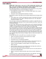
Intermittents
IMPORTANT: Problem may or may not turn “ON” the Malfunction Indicator Lamp
(MIL) or store a DTC. DO NOT use the Diagnostic Trouble Code (DTC) tables for inter-
mittent problems. The fault must be present to locate the problem.
Most intermittent problems are caused by faulty electrical connections or wiring. Perform
careful visual/physical check. Check for the following conditions:
•
Poor mating of the connector halves, or a terminal not fully seated in the connector
body (backed out or loose).
•
Improperly formed or damaged terminals and/or connectors.
All connector terminals in the problem circuit should be carefully checked for proper contact
tension.
•
Poor terminal to wire connection (crimping).This requires removing the terminal from
the connector body to check. Refer to “Wiring Harness Service” in the “Description
and System Operation” section.
The vessel may be driven with a Digital Multimeter connected to a suspected circuit. An
abnormal voltage when malfunction occurs is a good indication that there is a fault in the
circuit being monitored.
A scan tool (see “Special Tools” for part numbers) can be used to help detect intermittent
conditions. The scan tools have several features that can be used to locate an intermittent
condition. The following features can be used in finding an intermittent fault:
The “Record” feature or choosing not to erase data can be triggered to capture and store
engine parameters within the scan tool when the malfunction occurs. This stored informa-
tion can then be reviewed by the service technician to see what caused the malfunction.
To check loss of DTC memory, disconnect TP sensor and idle engine until the MIL comes
“ON.” A trouble code should be stored and kept in memory when ignition is turned “OFF.”
If not, the ECM is faulty. When this test is completed, make sure that you clear the DTC 22
from memory.
An intermittent MIL with no stored DTC may be caused by the following:
•
Ignition coil shorted to ground and arcing at ignition wires or plugs.
•
MIL wire to ECM shorted to ground.
•
Poor ECM grounds, Go to ECM wiring diagrams.
•
Check for an electrical system interference caused by a sharp electrical surge. Nor-
mally, the problem will occur when the faulty component is operated.
•
Check for improper installation of electrical options such as lights, ship to shore
radios, sonar, etc.
•
Check that knock sensor wires are routed away from spark plug wires, ignition sys-
tem components and charging system components.
•
Check for secondary ignition components shorted to ground, or an open ignition coil
ground (coil mounting brackets).
•
Check for components internally shorted to ground such as starters, alternators or
relays.
All Ignition Control (IC) module wiring should kept away from the alternator. Check all wires
from the ECM to the ignition control module for poor connections.
Index

