DIAGNOSTICS
SERVICE MANUAL NUMBER 24
Page 5G-64
90-861327--1 OCTOBER 1999
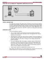
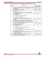
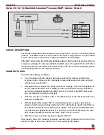
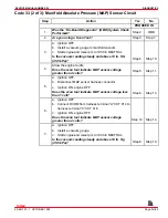
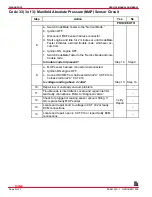
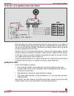
Code 23 (1 of 3): Intake Air Temperature (IAT) Sensor Circuit
A
B
ECM
MEFI 3
J2-30
J2-3
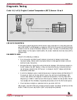
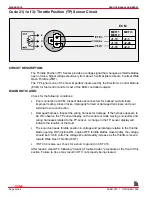
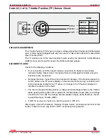
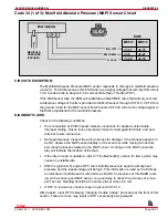
CIRCUIT DESCRIPTION:
The Intake Air Temperature (IAT) Sensor uses a thermistor to control the signal voltage to
the ECM. The ECM applies a voltage on CKT 472 to the sensor. When the intake air is cold,
the sensor (thermistor) resistance is high, therefore, the ECM will see high signal voltage.
As the intake air warms, the sensor resistance becomes less, and the voltage drops. At nor-
mal engine operating temperature, 160-180
°
F (71-82
°
C), the voltage will measure about
1.5 to 2.0 volts.
DIAGNOSTIC AIDS:
Check for the following conditions:
•
Poor connection at ECM. Inspect harness connectors for backed out terminals,
improper mating, broken locks, improperly formed or damaged terminals, and poor
terminal to wire connection.
•
Damaged harness. Inspect the wiring harness for damage. If the harness appears to
be OK, observe the IAT display on the scan tool while moving connectors and wiring
harnesses related to the IAT sensor. A change in the IAT display will indicate the
location of the fault.
•
The scan tool displays intake air temperature in degrees Celsius and Fahrenheit. If
the intake air is cold (not running within 8 hours), the scan tool should display a IAT
sensor value within a few degrees of outside air temperature. This may help aid in
diagnosing a “shifted” sensor. After engine is started, the temperature should rise
steadily and then stabilize at operating temperature.
•
If DTC 21 is also set, check for open ground CKT 813.
After repairs, clear DTC following “Clearing Trouble Codes” procedure at the front of this
section. Failure to do so may result in DTC not properly being cleared.
Index

