DIAGNOSTICS
SERVICE MANUAL NUMBER 24
90-861327--1 OCTOBER 1999
Page 5G-79
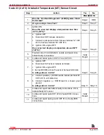
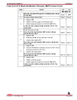
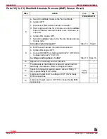
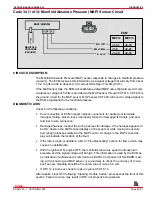
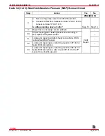
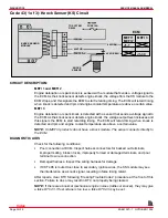
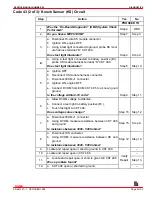
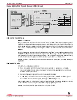
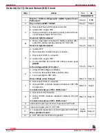
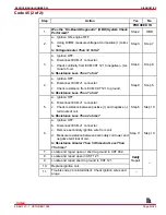
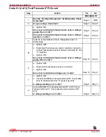
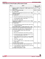
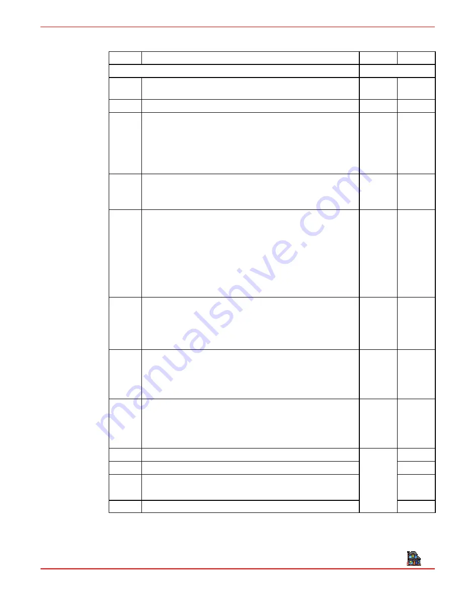
Code 43 (2 of 3): Knock Sensor (KS) Circuit
Step
Action
Yes
No
PROCEED TO
1.
Was the “On-Board Diagnostic” (OBD) System Check
Performed?
Step 2.
OBD
2.
Do you have a MEFI 3 ECM?
Step 7.
Step 3.
a. Disconnect 5-wire KS module connector
b. Ignition ON, engine OFF.
3.
c. Using a test light connected to ground, probe KS mod-
ule harness terminal “B” CKT 439.
Does test light illuminate?
Step 4.
Step 9.
4.
a. Using a test light connected to battery positive (B+),
probe KS module harness terminal “D” CKT 486.
4.
Does test light illuminate?
Step 5.
Step 10.
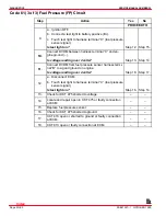
a. Ignition OFF
b. Reconnect KS module harness connector.
c. Disconnect ECM J1 connector.
5.
d. Ignition ON, engine OFF.
e. Connect DVOM from ECM CKT 485 to a known good
ground.
Is the voltage within 8-10 volts?
Step 6.
Step 11.
a. Allow DVOM voltage to stabilize.
b. Connect a test light to battery positive (B+).
6.
c. Touch test light to CKT 496.
Does voltage value change?
Step 15. Step 12.
7.
a. Disconnect ECM J1 connector
b. Using DVOM, measure resistance between CKT 496
and ground.
Is resistance between 3000 - 5000 ohms?
Step 15.
Step 8.
8.
a. Disconnect KS connector.
b. Using DVOM, measure resistance between KS and
ground.
Is resistance between 3000 - 5000 ohms?
Step 12. Step 14.
9.
Locate and repair open or short to ground in CKT 439.
–
10.
Locate and repair open in CKT 486.
–
11.
a. Locate and repair open or short to ground in CKT 485.
Was a problem found?
Verify
Repair
Step 13.
12.
a. CKT 496 open or shorted to ground.
–
Index

