GENERAL
SERVICE MANUAL NUMBER 24
90-861327--1 OCTOBER 1999
Page 7A-3
MIE (Inboard) Engines
When designing and installing exhaust system, it is very important that the following addi-
tional points be taken into consideration:
1. System layout and construction must prevent cooling system discharge water from flow-
ing back into engine and also must prevent seawater from entering engine via exhaust
at any point.
2. The exhaust hoses and pipes must not be higher than exhaust elbows at any point.
3. The exhaust outlet (for routing exhaust to outside of boat) must be located so that a mini-
mum of 1/2 in. (13 mm) per foot (305 mm) downward pitch (drop) exists in the exhaust
hose or pipe from the engine exhaust elbow to the outlet, with a minimum drop of 4 in.
(102 mm) overall. (This is an American Boat & Yacht Council recommendation.) The
drop must be constant so that a low spot does not exist at any point in the exhaust hose
or pipe.
4. Exhaust outlet must be slightly above the waterline with boat at rest in the water and full
load aboard. Exhaust outlet should be equipped with an internal shutter to prevent sea-
water from running back into exhaust system. The use of an exhaust flapper on each
outlet also is recommended.
5. System must not cause excessive back pressure. Back pressure MUST NOT exceed
4 in. (102 mm) of mercury when measured with a mercury manometer at exhaust elbow
outlets. Minimum exhaust hose sizes are given in chart.
Minimum Hose Size
Model
Single Outlet
Dual Outlet
All
4 in. (102 mm)
3 in. (76 mm)
Exhaust Hose Connection
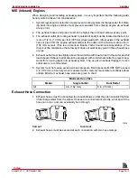
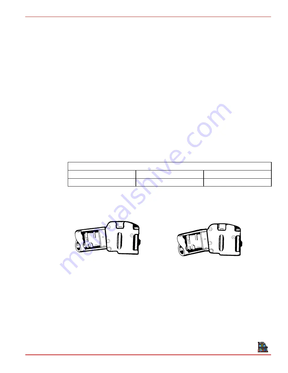
1. Exhaust hoses must be connected to exhaust elbows so that they do not restrict the flow
of discharge water from the elbow. If hoses are connected incorrectly, a hot spot in the
hose can occur, and can eventually burn through.
72538
Correct
Incorrect
2. Exhaust hoses must be secured at each connection with two hose clamps.
Index

