STARTING SYSTEM
SERVICE MANUAL NUMBER 24
Page 4A-4
90-861327--1 OCTOBER 1999
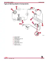
Positive Current Flow
This is a general description of the positive current flow from the battery through the system
until the starter motor cranks.
NOTE: Check that all connections are tight and have the required resistance.
•
Battery to the solenoid switch (on starter) (RED battery cable).
•
Solenoid switch to circuit breaker (RED).
•
Circuit breaker to wire junction (RED-PUR).
•
Wire junction to wiring harness plug (RED-PUR) terminal 6.
•
Wiring harness plug to 20 amp fuse (RED-PUR).
•
20 amp fuse to ignition switch terminal I (RED-PUR). At this point ignition switch is
turned to START.
•
Ignition switch terminal I to terminal C.
•
Ignition switch terminal C to neutral start switch (YEL-RED). NEUTRAL START
SWITCH MUST BE AT NEUTRAL POSITION.
•
Neutral start switch to wiring harness plug terminal 7 (YEL-RED).
•
Wiring harness plug to starter solenoid (small terminal) (YEL-RED). Also ensure that
black (small terminal) wire is grounded.
•
Starter solenoid is now “closed,” completing circuit between large terminal
(RED-PUR) and other large terminal (YEL-RED), causing starter motor to crank.
Battery
Battery Cable Recommendations
IMPORTANT: Terminals must be soldered to cable ends to ensure good electrical
contact. Use electrical grade (resin flux) solder only. Do not use acid flux solder as
it may cause corrosion and failure.
Cable Length
Cable Gauge
Up to 3 - 1/2 ft (1.1m)
4
(25 mm
2
)
3-1/2 - 6 ft (1.1-1.8m)
2
(35mm
2
)
6 ft - 7-1/2 ft (1.8-2.3m)
1
(50mm
2
)
7-1/2 - 9-1/2 ft (2.3-2.9m)
0
(50mm
2
)
9-1/2 - 12 ft (2.9-3.7m)
00
(70mm
2
)
12 - 15 ft (3.7-4.6m)
000
(95mm
2
)
15 - 19 ft (4.6-5.8m)
0000
(120m
2
)
Both positive (+) and negative (–) cables
Index

